Selective Soldering: Preparation, Placement and Process Control
Through hole parts did not disappear when surface mount took over. Connectors, relays, transformers and anything that has to survive a mechanical load are still inserted and soldered, and on a board that is otherwise reflowed, through hole joints are made in a second operation. Selective soldering is the way that second operation is controlled.
The alternative, hand soldering every joint, depends on operator skill and is difficult to reproduce. A selective machine brings a small solder wave to each joint in turn under program control, which makes the flux, the heat and the solder volume repeatable. The process window is narrow, and understanding it is most of the work.
How the Process Works
A selective machine has a small nozzle that produces a miniature wave, typically a few millimetres across, which is brought into contact with the underside of the board at the point where a joint is to be made. The board is held above the nozzle on a pallet or in a fixture, and the nozzle moves from joint to joint following a program.
Flux is applied first, either by spraying the whole board or by depositing a small amount at each site with a dispenser. The board is then preheated, usually from below with an infrared or a hot air module, and the nozzle wave completes the joint. Each of those steps has its own parameters and its own effect on the result.
Flux Deposition and What It Leaves Behind
Flux deposition decides whether the joint wets. Too little and the oxide on the pin and the barrel is not removed; too much and the residue becomes a problem for the cleaning step and for any coating that follows. Spray fluxing over the whole board is fast and generous, while point fluxing is precise and leaves less material.
The choice interacts with the requirement for cleanliness. A no clean process has to leave a residue that is safe to leave on the board, which places a limit on the flux chemistry and on the amount applied. A product that will be conformally coated usually needs a cleaning step, and the residue from the selective process has to be compatible with it.
Thermal Profile in a Selective Machine
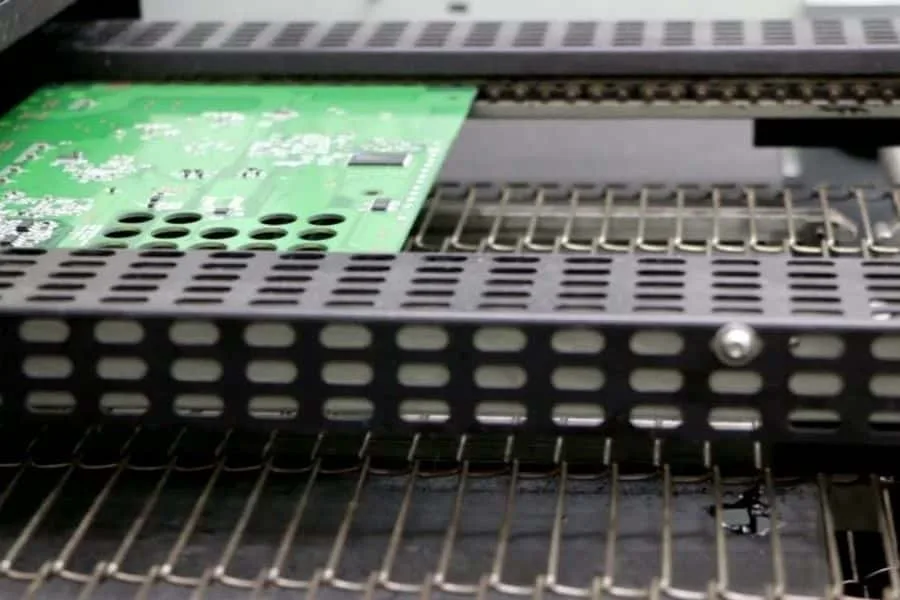
The thermal profile is built from the preheat and the contact time in the wave. A large connector with a heavy thermal mass needs more preheat than a small relay, and the two may share the same board. Where that happens, the profile has to be set for the most demanding joint, and the others are then exposed to more heat than they need.
Preheating from below raises the whole board towards the soldering temperature and reduces the time the wave has to spend on each joint. That protects the laminate and the nearby surface mount parts, but it also brings the whole assembly closer to the temperature at which the reflowed joints on the top side begin to soften. Balancing the two is the core of the process.
Nozzle Choice and Wave Stability
The nozzle diameter and shape determine the size of the contact area and how much solder is available at the joint. A nozzle that is too small cannot deliver enough heat for a heavy joint, while one that is too large floods the area and can bridge to neighbouring pins. The selection follows from the pitch and the thermal mass of the part.
Wave stability matters as much as size. A nozzle that is partly blocked produces a wave that is uneven and a joint that wets on one side only, and the blockage develops gradually as oxide accumulates. Regular maintenance and a defined cleaning interval are part of the process, not an optional extra.
Fixtures, Pallets and Support
The board has to be held flat and at a defined height above the nozzle, because the contact between the wave and the joint depends on that geometry. A pallet with properly placed support pins keeps the board flat and protects the surface mount components on the underside from the flux and the heat.
The fixture also determines which joints are accessible. A pin placed under a joint prevents the wave from reaching it, and a mask that is too tight around a connector can prevent the solder from forming a proper fillet. Designing the fixture together with the process program is what avoids those conflicts.
Inspection of a Through Hole Joint
A good joint has a fillet that rises up the pin on both sides and wets the barrel. Judging it optically is possible from the top and the bottom, and a joint that looks acceptable can still hide a barrel that was not filled. Where the product is critical, a cross section or an X-ray check of the first article is the way to confirm the process.
Visual criteria for through hole joints should be written down for the operators, including the acceptable fillet height and the defects to look for: insufficient fill, excess solder forming a ball, icicles, and the web of solder that forms between two adjacent pins when the flux or the nozzle is wrong. The same discipline of written criteria and recorded results is what makes the quality control routine mean something.
Interaction with the Reflow Step
Because the selective operation heats the whole assembly, the joints made during reflow are exposed to a second thermal cycle. Parts that were attached with a low temperature alloy may be at risk, and the sequence of the two operations matters when the board carries both types of joint.
The usual arrangement is to reflow first and selectively solder the through hole joints afterwards, accepting that the second step is carried out at a lower peak temperature than the first. Where that is not possible, the alternative is to place the through hole parts last and use a solder alloy with a lower melting point, which brings its own constraints, and the alloy comparison is the one set out in the discussion of lead free versus leaded solder.
Process Control and Records
The parameters that have to be recorded are the flux type and amount, the preheat temperatures and times, the nozzle size and the contact time for each joint. Together they define the process, and a change in any of them changes the result, so the record is what allows a second run to reproduce the first.
The records also support the maintenance schedule, because the drift in the process is mostly caused by the machine: a nozzle that has worn, a heater that responds more slowly, a flux system whose spray pattern has changed. Checking those against the specified values at the start of a shift is what keeps the process inside its window.
FAQ
Can selective soldering replace wave soldering? For boards with only a few through hole parts it usually does, because it avoids masking the whole underside. A board with many through hole components is still faster in a wave.
How much flux is enough? Enough to wet the joint within the time the wave allows. The amount is set by the spray or dispense parameters and confirmed by the appearance of the fillet.
Is cleaning necessary after selective soldering? It depends on the flux and on what follows. A no clean flux may be left in place, while a coated product usually needs the residue removed, which is the same judgement described in the notes on the cleaning process.