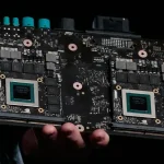
Development Board PCB Design for Embedded Platforms
A development board exists to expose every interface of a processor, which makes it a different design problem from a product. Development board pcb design is judged by how many interfaces reach a connector and how easily the software team can reach them.
What a Development Board Is For
The board is a platform for software development, hardware bring up and evaluation. It carries the processor, the memory, the power stage and a connector for every interface that the processor supports.
That purpose defines the layout. Signals that would be hidden on a product board are brought out, and test points are placed where an engineer can reach them with a probe.
Choosing the Processor and Memory
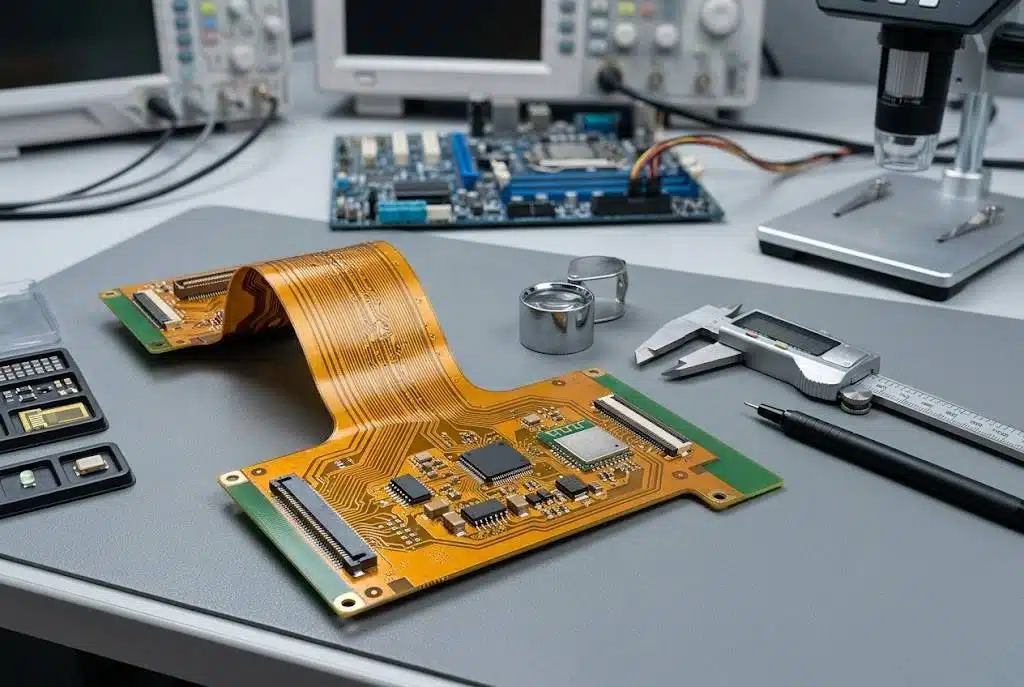
The processor is chosen for the interfaces it supports rather than for its peak performance. The memory follows from the processor, and the type, the width and the speed are usually fixed by the device.
A development platform often needs more memory than the final product, because debug builds and development tools consume it. Under sizing the memory is a mistake that cannot be corrected later.
Using the Vendor Reference Design
A vendor reference design or evaluation board is supplied with the device, and its layout has been validated by the manufacturer. Following it reduces the risk in the memory and power sections dramatically.
The reference design is followed most closely where the timing is critical, which means the memory bus and the power delivery. Departing from it in those areas is what turns a working design into an intermittent one.
Stackup and Layer Count
A platform of this kind typically needs six to eight layers, with a thin dielectric between the outer layer and the first plane. A board of about one hundred and fifty by one hundred millimetres at one and a half millimetres thick is a common size.
Minimum feature sizes of four mil lines and spaces with eight mil vias are achievable on a standard process and are enough for the escape and the memory bus. Pushing below them raises the price without improving the platform.
LPDDR Memory Routing
Memory is routed as a group per byte lane, with the lengths matched within the group and the clock treated separately. The reference plane under the bus is continuous from the processor to the memory device.
Routing lpddr on a development board is easier than on a product because there is space. The temptation to spread the bus out should be resisted, since a longer path makes the timing harder rather than easier.
Power Architecture
The power stage provides several rails with defined voltage, current and sequence. A dedicated power management device is normally used, and its programming is part of the firmware rather than the layout.
Power sequencing is enforced by the device, but the board still has to place the capacitors, the inductors and the sense connections correctly. The switching loops are kept small, and the sensitive analogue rails are filtered at the load.
Expansion Headers
Expansion headers are what make the board useful, and their pinout is a design decision. Grouping signals by function, with grounds between groups, reduces crosstalk and makes the header easy to use.
Each expansion header should carry its own ground and supply pins, and the pinout should be documented before the board is ordered. A header that is wired during layout rather than by design is a source of errors for years.
Debug and Programming
A development board needs a debug port more than a product does. The connector is placed where a probe can reach it while the board is running, and the reset and boot mode signals are brought out beside it.
Boot configuration straps are set with links rather than with solder bridges, so that a different boot source can be selected without a soldering iron. The same applies to the recovery mode selection.
Display and Camera Connectors
Display and camera interfaces need connectors that survive repeated mating, because they will be plugged and unplugged during development. A fine pitch board to board connector is a poor choice for that role.
The high speed pairs are routed with matched lengths, and the connectors are placed so that the cables do not cross the memory or the power section. Cable routing matters as much as the trace routing.
Network and USB
Ethernet, USB host and USB device ports are expected on a development platform. The connectors are placed on one edge, and their return paths are kept out of the memory and power sections.
Where a connector is on a long cable, protection is added. A development board is handled constantly, and an unprotected port is the most likely thing to be damaged.
Audio and User Interface
Audio inputs and outputs, a few buttons and several status indicators make the platform usable without extra hardware. The audio path is kept away from the switching supplies for the same reason as on any other board.
Buttons and indicators are connected to the processor through the same headers that expose the general purpose pins, which keeps the firmware flexible.
Mechanical Form Factor
Development platforms are often built to a published form factor so that they fit existing cases and accessory boards. The mounting holes and the connector positions then follow a standard rather than the design.
Where the form factor is defined, the layout begins from the mechanical drawing. Our notes on board outline and mounting describe how those constraints are applied.
Bring Up Order
Bring up begins with the power rails and the clock, then the debug port, then the memory training and finally the peripherals. Each stage is confirmed before the next one is attempted.
A documented bring up order is part of the deliverable of a development platform. It is what allows a new user to get the board running without the designer in the room.
Documentation for Users
The platform needs a schematic, a bill of materials, a layout drawing and a description of every header. Without them the board is a sample rather than a platform.
Documenting the boot selection, the connector pinouts and the test points is the difference between a board that is used and one that is put in a drawer. The release package follows the same practice as any PCBA development project.
Manufacturing Notes
The board is usually built in small quantities, so the design should avoid processes that only make sense at volume. Standard stackups, standard finishes and standard via sizes keep the cost and the lead time predictable.
Assembly is simplified by keeping the parts on one side where possible and by using packages that can be placed and reworked. A development board that cannot be reworked is useless to the team that has to debug it.
Related reading: our fabrication notes, board quality and design release notes cover the same ground.
FAQ
Should the memory layout copy the reference design exactly? Where the timing is critical, yes. The routing may be moved on the board, but the topology, the length matching and the reference planes should follow the validated arrangement.
How many layers does a development board need? Six to eight is typical for a processor with an external memory bus, with a thin dielectric to the first plane.
Why bring out signals that the product will not use? Because the platform is used for evaluation and software development. A signal that cannot be reached costs the software team far more than the header costs the board.