
High Current PCB Trace Current Capacity and Copper Thickness Tolerance Design
In high power electronic systems, the current carrying capacity of PCB traces is directly related to the reliability of the entire machine and the thermal safety boundary. Traditional design often relies on empirical charts in IPC-2221 or IPC-2152 standards for rough estimation, but these methods do not fully consider key variables introduced by the manufacturing process, especially the negative tolerance of copper foil thickness. In actual mass production, electrolytic copper foil, or ED, or rolled copper foil, or RA, often has a thickness deviation of plus or minus 10 to 15 percent after etching, and negative deviation is dominant. For example, for an inner layer circuit with a nominal 2 oz, or 70 micrometer, copper thickness, after pattern etching and solder mask coverage, the measured average copper thickness may be only 58 to 62 micrometers. If surface treatment is superimposed, such as about 0.3 to 0.5 micrometers of nickel and gold layers in the ENIG immersion gold process that contribute nothing to current carrying, the effective conductive cross-sectional area loss can reach more than 18 percent. If this deviation is not modeled and compensated in the initial design stage, it will lead to excessive temperature rise, accelerated copper migration, and even local fusing.
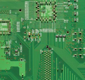
Engineering Correction Necessity of IPC-2152 Current Capacity Model
The IPC-2152 standard establishes a multi-dimensional relationship between trace temperature rise, or delta T, and current, trace width, copper thickness, dielectric layer structure, and environmental heat dissipation conditions through a large amount of experimental data. Its core formula is I equals k times delta T to the power b times W to the power c times T to the power d, where k, b, c, and d are fitting coefficients that vary depending on trace location, inner or outer layer, presence of reference plane, and copper thickness range. However, this standard assumes nominal copper thickness by default, and test samples are taken from idealized laboratory processes. In engineering practice, a manufacturing tolerance factor gamma must be introduced to correct the copper thickness term: Teff equals Tnominal times 1 minus delta, where delta is the negative tolerance rate with a recommended value of 0.12 to 0.15. For outer layer traces, the influence of surface treatment layers on thermal resistance must also be superimposed. In the ENIG process, the thermal conductivity of a 0.2 micrometer nickel layer is only 25 percent that of copper, significantly hindering lateral heat conduction to the copper area and increasing equivalent thermal resistance by about 7 to 10 percent. Therefore, the corrected current capacity should be recalculated as Idesign equals IIPC2152 times 1 minus delta to the power d, ensuring that delta T of 30 degrees Celsius or less, the general industrial safety threshold, is still met under the most unfavorable copper thickness conditions.
Thermal-Electrical Coupling Simulation Verification and Key Parameter Sensitivity Analysis
Relying solely on analytical formulas has limitations, especially in complex stack-ups such as high-frequency and high-speed mixed high current PCB paths, non-uniform heat dissipation such as local shield coverage, or variable width traces. At this time, thermal-electrical coupling simulation tools based on the finite element method, or FEM, such as ANSYS Electronics Desktop or Siemens Simcenter 3D, should be used. When modeling, the measured copper thickness distribution must be accurately input. Monte Carlo sampling is recommended, using a normal distribution of N with mu equal to 0.87 times Tnom and sigma equal to 0.03 times Tnom to simulate 100 groups of samples and calculate the minimum current carrying capacity at the 95 percent confidence interval. A certain 48 V and 60 A power management board case shows that in a 2 oz outer layer trace, when copper thickness drops from the nominal 70 micrometers to 59 micrometers with delta equal to 0.157, the steady-state temperature rise of the same 3 mm wide trace at 100 degrees Celsius ambient jumps from 42 to 68 degrees Celsius, exceeding the 60 degrees Celsius upper limit allowed by UL60950-1. Further analysis shows that when trace length is greater than 15 mm, the heat convergence effect at the end pad makes the local hot spot temperature rise 12 degrees Celsius higher than the theoretical average. This phenomenon is easily overlooked in conventional calculations.
PCB design

Layered Design Strategy for Safety Margin
To systematically avoid manufacturing deviation risk, a three-level safety margin design is recommended. The first level is material level margin, requiring PCB manufacturers to provide copper foil batch thickness inspection reports and clearly specifying minimum guaranteed copper thickness in procurement specifications, such as 2 oz copper requiring 61 micrometers or more, rather than only marking the nominal value. The second level is design level margin, adding an additional 15 to 20 percent width redundancy on the basis of IPC-2152 calculation. For example, if calculation requires 2.4 mm width, actually set 2.8 mm. This redundancy can effectively offset etching undercut, usually 0.05 to 0.08 mm per side, and copper thickness negative deviation. The third level is functional level margin. For critical paths such as the main battery charge and discharge loop, a dual parallel trace structure is mandatory, with a spacing of 3 mm or more between the two traces to avoid thermal coupling, and each independently meeting 100 percent rated current carrying requirements. A certain automotive OBC module adopted this strategy. It split the 400 A main power trace into 4 groups of 100 A sub-paths, each using 4 mm wide by 70 micrometer copper thickness outer layer traces. Measured results show that even when copper thickness is as low as 57 micrometers, delta T is still maintained at 28 degrees Celsius, verifying the effectiveness of layered margin.
Manufacturing Process Feedback Closed Loop and DFM Collaborative Optimization
Safety margin design cannot operate in isolation from manufacturing capability. A DFM, or design for manufacturability, collaboration mechanism between PCB factories and designers must be established. First, embed a copper thickness tolerance annotation layer in the Gerber output stage, such as adding a COPPER_TOLERANCE: -12% note on the Mechanical layer. Second, the first article inspection report must include XRF, or X-ray fluorescence, measured copper thickness data, comparing with design expectations to form a deviation trend chart. Finally, for three consecutive batches with copper thickness below the lower limit, trigger a process review. Common root causes are etching solution concentration decay or excessive transmission speed. A certain communication base station power board project, through this closed loop, increased copper thickness CPK, or process capability index, from 1.03 to 1.42, corresponding to a reduction in negative tolerance occurrence rate from 12.6 to 2.1 percent. It is worth noting that using reverse etch process can improve copper thickness control precision to within plus or minus 5 percent, but the cost increases by about 18 percent, suitable for ultra-high reliability scenarios such as aerospace or medical.
Measured Verification Methods and Failure Boundary Determination
The final design must be verified by measurement. A stepped current loading method is recommended. Start at 1.2 times the rated current, increase by 0.1 times every 10 minutes, and simultaneously monitor the full-domain temperature distribution of the trace with an infrared thermal imager with spatial resolution of 0.5 mm or less. There are three key determination points. First, if temperature rise delta T at any position continuously exceeds 60 degrees Celsius, it is judged as the thermal failure critical point. Second, if the temperature difference between the middle of the trace and the pad connection exceeds 15 degrees Celsius, it indicates insufficient pad thermal design. Third, if at 1.5 times rated current for 30 minutes there is no copper discoloration, or oxidative blackening, or resistance drift greater than 5 percent, the design margin is confirmed to be sufficient. A certain server VRM module measurement found that a 3 oz trace without reserved tolerance margin showed local copper grain coarsening at 1.3 times load. SEM analysis showed grain boundary oxidation depth reached 1.2 micrometers, confirming that the early failure mechanism had been initiated at the microscopic level. Therefore, not burning out does not equal safety. Microstructure degradation is the more essential failure criterion.
In summary, the essence of high current PCB design is manufacturing uncertainty management. Only by embedding copper thickness negative tolerance as a core variable into the calculation model, combined with thermal-electrical simulation, layered margin, and process closed loop, can a robust balance be achieved among cost, volume, and reliability. A design that ignores this variable, no matter how perfect its theoretical calculation, will expose unpredictable thermal risks in the mass production stage.
Gopcba provides professional PCB manufacturing, PCB assembly, prototype PCB assembly, low-volume PCB assembly, high-volume PCB assembly, SMT PCB assembly, through-hole PCB assembly, mixed-technology PCB assembly, flex PCB assembly, PCB design layout, components procurement, rapid PCBA prototyping, conformal coating, PCBA testing, box build assembly, wire cable harness assembly, medical PCBA, telecommunications PCBA, energy PCBA, industrial PCBA, artificial intelligence PCBA, Internet of Things PCBA, PCB capabilities, and PCBA capabilities. You can also visit our blog, learn about us, see why us, review our quality management, or contact us for more information.