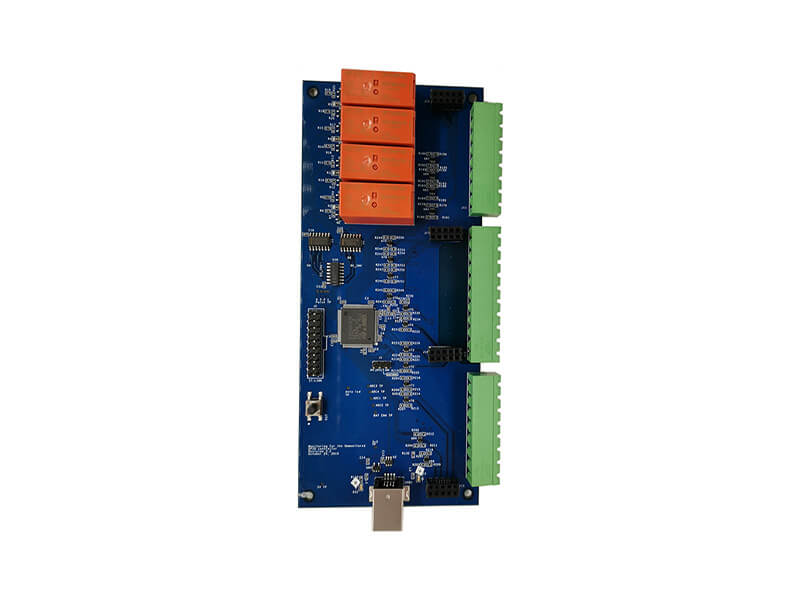
Digital Isolator Circuit Design
A digital isolator passes logic levels across an isolation barrier, and it has replaced the optocoupler in most new designs. The advantages are a shorter and more consistent delay, a longer life and a lower power consumption, and the layout rules are stricter than they look.
How the Channel Works
An input stage converts the logic level into a signal that the barrier can carry, which is either a modulated carrier or a pair of pulses. The receiving side reconstructs the level, and a watchdog at the output returns it to a defined state if the pulses stop.
That watchdog behaviour is important. A part with a default output state holds the line at a defined level when the input side loses power, and the choice of default high or default low decides the behaviour of the system in that condition.
The barrier is capacitive or magnetic, and its capacitance is a few picofarads per channel. That capacitance is what couples the common mode transient, and it is also what makes the part sensitive to a fast voltage difference.
Channel Direction and Configuration
An isolator with fixed directions suits a bus where the data flows one way. A bidirectional part or a pair of parts is needed where the direction changes, such as on a serial bus with a shared line.
The direction control of a bidirectional isolator has to be fast enough for the protocol, and its own delay adds to the round trip time. Where the protocol has a tight turnaround, the delay budget has to include both the isolator and the transceiver.
A part with an integrated transceiver and isolator is convenient and it fixes the direction internally. The trade is that the electrical specification is no longer under the designer’s control.
propagation delay and channel matching
propagation delay is the time from the input edge to the output edge, and it is specified with a maximum and a variation with temperature. channel matching is the difference in delay between channels of the same package.
A parallel bus that crosses an isolator has to keep its channels matched, or the data arrives skewed. The matching specification is the number that matters for a parallel interface, and it is usually much smaller than the absolute delay.
For a serial interface the absolute delay matters and the matching does not. The two specifications are often confused, and choosing a part for the wrong one leads to a design that works in the laboratory and fails in the field.
The isolated supply
Each side of the barrier needs its own supply, and the isolated side needs a supply that is itself isolated. A small transformer with a rectifier, or an integrated isolated converter, provides a few tens or hundreds of milliwatts.
The supply has to be quiet, because the switching of the converter couples into the signal path if the layout is poor. A ferrite and a capacitor on the isolated side, placed close to the isolator, reduce the coupling.
The isolation rating of the supply has to match that of the signal channel. A barrier that is rated for five kilovolts with a supply rated for one is rated for one, and the mismatch is a common oversight.

transient immunity and Its Measurement
transient immunity is the rate of change of the barrier voltage that the part can withstand. It is measured by applying a fast step across the barrier and watching the output for a wrong state.
The result depends on the layout as much as on the part. A layout with the two sides separated and no copper crossing the barrier keeps the coupling capacitance at the package value, while a layout with a plane underneath adds to it.
Where the transient immunity is marginal, a second barrier in series or a different technology is the answer rather than more filtering. Filtering at the output cannot remove a state that has already been latched.
Layout of the Two Domains
Keep the primary and the secondary copper strictly on their own sides, with no track passing under the package. The recommended layout in the datasheet is usually the minimum rather than an example.
Decouple each supply pin with its own capacitor, placed within its own domain. A capacitor that spans the barrier is a short circuit for the coupled transient and it removes the isolation.
Route the signal traces so that the two sides do not run parallel to each other on opposite layers. Parallel traces form a capacitor across the barrier, and the value can exceed the internal one if the traces are long.
Default State and Fail Safe Behaviour
The default output state decides what the system does when the input side loses power. A logic level that enables a driver should default to the disabled state, and one that releases a brake should default to the safe state.
The choice is made in the part number, which means it is made in the bill of materials rather than in the firmware. It deserves a line in the design description, because the failure behaviour of the product depends on it.
Some parts also have an enable input that puts the output into a high impedance state. That allows a bus to be shared between several isolators, and it has to be handled with a pull up or pull down so that the state is defined.
Choosing a Part for the Interface
A serial bus at a few hundred kilobaud needs a delay below a few tens of nanoseconds and does not care about matching between channels. A parallel bus running at ten megabits needs matching of a nanosecond or better and a delay that is stable over temperature.
A gate drive signal needs the shortest possible delay, because it sets the dead time of the bridge, and its default state matters more than its speed when the input side loses power.
The power consumption of the isolator belongs in the budget of a battery product, and it rises with the data rate. A part that is efficient at a low rate can draw milliamps per channel at a high one.
Verification and Faults
Verify the channel by measuring the delay at the output with a fast edge at the input and a probe of low capacitance. The delay and the rise time are the numbers to record, and both change with temperature.
Apply a common mode step across the barrier with a fast generator and watch for a change in the output. The test is the only way to confirm the immunity of the actual layout.
A channel that works at room temperature and fails when hot usually has a delay that has grown beyond the timing margin of the interface. The release checks that keep such a barrier consistent are collected in our PCB design release checklist, the assembly points in judging PCB quality, and the layout measures for two domains in our guide to mixed signal board design.
FAQ
What replaces an optocoupler with a digital isolator? Timing, life and power all improve. The layout requirements become stricter, because a capacitive barrier couples a fast transient.
What is channel matching? The difference in delay between channels of one package. It matters for a parallel bus and not for a serial link.
Can a plane run under an isolator? No. It adds capacitance across the barrier and reduces the transient immunity, sometimes below the specification.