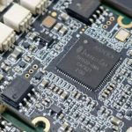
Chip Component Crack Causes in SMT Assembly
A cracked chip component is one of the most common defects on a mature assembly line, and it is also one of the least visible. The body may look intact while a fracture runs through the ceramic, and the part passes final test because the crack has not yet opened the electrode.
Because the failure appears later, the usual report from the field is a board that worked during production and failed during temperature cycling or after a mechanical shock. Understanding the mechanisms that create the crack is what allows the process to be corrected before the parts are shipped.
Where the Stress Comes From
A chip component is a rigid ceramic body soldered to a laminate that expands and contracts at a different rate. Every temperature change therefore applies a shear force through the joints and into the body, and the body is the part that cannot deform.
The force is proportional to the distance between the two joints, so a larger case size experiences more stress than a small one for the same temperature swing. That single fact explains why 1206 and larger bodies crack more often than 0402 parts on the same board.
Bending Stress During Handling
Most cracks are created mechanically rather than thermally. A board that is flexed during depanelling, during a connector insertion or during a test fixture applies a bending moment that transfers directly into the solder joints and from there into the ceramic.
The direction of the bend matters as well. A component placed near a break line or near a mounting screw sees the highest curvature, and one placed with its long axis parallel to the bend resists better than one placed across it.
Placement and Nozzle Damage
A placement nozzle that descends too far presses on the body and can initiate a crack that is invisible until the part is in service. The damage is more likely on a thin part or on a large case size, and it is more likely where the nozzle is chosen for speed rather than for the body size.
Z axis force settings and nozzle tip condition are therefore part of the crack investigation. A worn tip concentrates the force on a small area of the body, and a wrongly sized tip can contact the terminations rather than the centre.
Solder Joint Geometry and Volume
The joint transfers the load, and its shape decides how much of that load reaches the ceramic. A joint with a thick fillet that climbs high on the termination applies a larger moment than a thin fillet with a small contact area.
Excess paste volume is therefore a crack risk as well as a bridging risk. Control of the deposit volume through the aperture and the stencil thickness is the same control that reduces both problems, and the relationship is described in the rules for pad design standards.
Thermal Shock and Rework
A hand iron applied directly to a chip component produces a temperature gradient across the body that no reflow profile creates. The gradient causes differential expansion, and the crack begins at the point where the iron touched.
Where rework is necessary, the heat should be applied to the pad through hot air from below or from a controlled nozzle, and the component should be removed with a tool that grips the body without bending it. Force applied while the solder is solid is the fastest way to crack a part that was previously good.
Depanelling and Singulation
Breaking a panel by hand transfers the whole breaking force into the boards, and any component close to the break line receives a share of it. The damage is proportional to how much the panel flexes before the tab snaps.
Supporting the board directly under the break line with a fixture removes most of the flex, and using a router or a laser removes it entirely. Where a product carries large ceramic parts, the depanelling method is worth choosing for the components rather than for the edge appearance.
Fixtures, Test and Screw Fixing
A test fixture that presses down on a populated board bends it, and the bend is repeated every cycle. A screw that is tightened without a support beneath it bows the board locally and cracks any component near the hole.
The remedy is mechanical: supports under the board at the test points, a washer or a boss to distribute the screw load, and a torque specification that the operator can follow. These are assembly decisions, but their consequences appear as component failures.
Materials and Termination Types
The termination material affects how much stress reaches the ceramic, because a compliant termination absorbs some of the movement before it is transferred. Components with a flexible termination are chosen for boards that will be bent or for assemblies that see large temperature swings.
The same applies to the alloy. A lead free joint is stiffer than a tin lead joint and transfers more stress into the body, which is one reason crack rates rose on some products after the transition. The comparison is discussed in the context of alloy selection.
Detection Methods
An optical inspection will not see a crack that does not reach the surface, so detection relies on other signals. A resistance measurement at final test may show a small change, and an acoustic or a bend test on a sample reveals cracks that the electrical test misses.
The standard sample test is a three point bend on a populated coupon, followed by a dye and pry examination or a cross section. The test is destructive and it is the only reliable way to know whether the process has changed.
Prevention and Process Discipline
Prevention comes from removing the sources rather than from inspecting the result. Support the board wherever it is handled, keep nozzles and forces within specification, control the paste volume, and choose a depanelling method that does not bend the boards.
Where a product must be handled roughly in service, the design should move large ceramic parts away from the edges, orient them with the bend direction and consider a compliant termination. Those choices cost little at layout time and save a field failure later.
Additional Considerations for This Build
Practical attention to chip component crack pays for itself here, because it decides whether the finished board behaves as the drawing intended. Where the requirement is not stated on the fabrication drawing or in the assembly notes, the shop has to assume a default, and that default is rarely the value the design was simulated with. Stating chip component crack explicitly, together with the tolerance that applies, removes the assumption and keeps the result predictable from batch to batch.
Deliberate attention to nozzle force pays for itself here, because it decides whether the finished board behaves as the drawing intended. Where the requirement is not stated on the fabrication drawing or in the assembly notes, the shop has to assume a default, and that default is rarely the value the design was simulated with. Stating nozzle force explicitly, together with the tolerance that applies, removes the assumption and keeps the result predictable from batch to batch.
Process Control and Verification
On a design of this kind, flexible termination is the item that decides how the rest of the board is arranged. Keeping a sample from the panel turns a dispute into a measurement, because the same coupon can be re-examined by both parties without rebuilding the batch. Reviewing the design before the data is released is cheaper than correcting it after the panel is in the tank, because every step downstream inherits the decision made at the front end.
Related reading: our fabrication notes, board quality and design release notes cover the same ground.
A first article check confirms that the process and the drawing agree on the points listed above, and that the coupon data supports the values used in the design.

Where a measurement falls outside the expected window, the sample is retained so that the cause can be established before the balance of the batch is released.
A first article check confirms that the process and the drawing agree on the points listed above, and that the coupon data supports the values used in the design.
Where a measurement falls outside the expected window, the sample is retained so that the cause can be established before the balance of the batch is released.
FAQ
Is a cracked part always a component defect? Rarely. Most cracks are created by handling, bending or process force, and the component supplier can usually demonstrate the difference with a cross section.
What is the strongest single preventive measure? Supporting the board under the point where force is applied, whether that force is a depanelling tool, a test probe or a screw.
Does a smaller case size eliminate the risk? It reduces it substantially, because the joints are closer together and the body is stiffer relative to the load, but it does not remove the need for careful handling.
How can a crack be found before shipping? Through a bend test on a sample from each build, since electrical test alone will not detect a fracture that has not yet opened the electrode.