Board Edge Plating And Routing Quality Control
The edge of a printed circuit board is the last surface to be produced and the first to be handled. It is cut from a panel that contains several boards, and the way it is cut decides whether the laminate delaminates, whether the copper layers are smeared, whether a burr is left standing, and whether an edge plating process can grip the material at all. The board edge is also the surface that a customer judges first, because it is visible without any instrument.
This article deals with how the outline is produced, what the cut does to the material, how edge plating and castellated features are made, and what has to be specified and inspected for the edge to be acceptable.
Where The Outline Comes From
The outline is defined in the fabrication drawing together with the routing path that the machine will follow, and it is normally placed on a dedicated layer rather than being inferred from the copper. The panel is designed around it, so the space between adjacent boards, the position of the tooling holes and the width of the rails are all decided at the same time as the board size, because a panel that cannot be depanelised cleanly will produce damaged boards regardless of how well they were built.
The edge has to be considered in three dimensions. The routed wall is cut through copper, resin and glass, and it will show the layers in section, which is why a controlled edge is sometimes required on a high frequency board to keep field lines away from the surface. The corner radius is set by the tooling, and a design that asks for an inside radius sharper than the cutter can physically make will be adjusted by the shop whether or not the drawing says so.

Routing, Scoring And Milling
Routing uses a rotating carbide cutter that is driven along the outline path, and it removes material rather than shearing it. The tool diameter sets the inside radius, the feed rate sets the cut quality, and the number of passes sets the load on the laminate. A slow, single pass with a sharp cutter gives a clean wall; a fast pass with a worn tool leaves a ragged edge and tears the glass bundles instead of cutting them.
Scoring, or V cutting, is different. Two bevelled wheels cut a groove along the top and bottom of the panel, and the boards are later broken apart along the groove. The technique is fast and leaves no gap between boards, so more boards fit on a panel, but it leaves a bevel and a small amount of exposed laminate at the break line, and a scored edge cannot carry edge plating. Milling with a small tool is used for internal cutouts and for the odd shapes that routing cannot reach.
What The Cut Does To The Material
A cutter generates heat and applies force, so the material near the cut is disturbed even when the cut looks clean. Resin can be smeared over the copper at the edge, glass bundles can be pulled out of the weave leaving a pitted surface, and the two can combine to produce a white or grey edge where the layers separate. On a multilayer board the same forces can open a gap between the copper foil and the resin that becomes a delamination after thermal cycling.
A burr is the material pushed out rather than cut off, and it appears most often on the copper on the exit side of the cut. A small burr is harmless mechanically, but it can bridge two nets if it is long enough to reach a neighbouring feature, and it is a handling hazard for anyone who has to move the board afterwards. Deburring is done with a brush or a puff of filtered air, and the brush itself has to be controlled, since an aggressive brush rounds the edge and removes mask.

Edge Plating And Castellated Features
An edge plating requirement turns the board edge into a plated surface. The panel is routed to a depth that stops short of the final outline, the edge is plated along with the walls of the holes, and the last cut then separates the boards. Because the plating is applied before the final cut, the area that will become the edge must be connected to the plating bus, and the design has to allow for the bus to be removed afterwards. The process needs the geometry to be arranged for it from the beginning, as described under PCB slot and edge routing rules.
Castellations are half holes along the edge, produced by drilling a hole whose centre lies on the outline so that the final cut leaves a plated semicircle. They are used to solder a module flat onto a carrier, and they need their own rules: the drill size, the annular ring, the distance between adjacent castellations and the position of the cut all have to be agreed with the shop. The mechanical arrangement around the edge is also part of the outline drawing, as explained under board outline and mounting design.
What Has To Be Specified
The drawing should state the outline dimension and its tolerance, the corner radius, the position and size of every cutout and slot, the requirement for edge plating or castellations, and the panelisation, including the rail width and the position of the fiducials that the assembly machines will use. Anything that is left out will be decided by the shop, and the shop will decide it in the way that suits its process rather than the way that suits the product.
Two details cause more trouble than the rest. The first is the tolerance on the outline, because a board that is 0.2 mm oversize may not fit its enclosure and one that is undersize may not be held by its connector. The second is the relationship between the outline and the copper, since a feature that is placed close to the nominal edge may be cut away by the tolerance. Both problems are avoided by keeping copper and mask a defined distance inside the nominal outline, as set out under board outline and mounting design.
Inspection And Acceptance
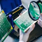
The edge is inspected visually for burrs, for white edges and for delamination, and with a low power microscope where an edge plating or a castellation is present. A cross section is taken when the edge forms part of a controlled impedance path or when a delamination complaint has to be resolved, and it shows the copper thickness on the wall and the condition of the laminate behind it.
Dimensions are checked against the drawing with a coordinate measuring machine or with an optical comparator, and the check is made on the finished board rather than on the panel. Where the edge carries plating, the thickness is measured at several points along the length, because the plating current density varies with the position on the panel and a single reading can hide a thin region.
FAQ
Why does the board edge look white or grey? The cut has disturbed the laminate and separated some of the glass bundles from the resin. A white edge is a cosmetic and sometimes a structural defect, and the usual cure is a sharper cutter with a slower feed.
Can a scored board be edge plated? No. Scoring removes the material that would carry the plating and leaves a bevel, so an edge plating requirement rules out V scoring for that board.
Who decides the corner radius? The shop does, in practice, because the radius is set by the smallest cutter that can be used at the required depth. The designer should specify a radius that the process can hold rather than a nominal value that implies a sharp corner.