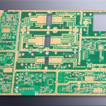
Panelization Spacing and Rail Width Rules for Assembly
A panel is a carrier for a group of boards, and every dimension on it exists to serve the machines that will process it. The rail that the conveyor grips, the gap between the boards, the position of the fiducials and the way each board breaks away are all decided at the panelization stage, and a mistake in any of them shows up as a machine fault or a broken component rather than as a drawing error.
Why Panelization Matters
Assembly equipment is designed to handle a panel of a defined size and stiffness, not a small board. The panel provides the edges that the conveyor grips, the area that the printer and the placement machine can support, and the surface on which fiducials and test coupons can be placed. Without it, many small boards could not be assembled at all.
The panel also determines how much material is consumed and how much handling the boards receive, because every time a panel is moved it carries several boards at once. A panel that is too dense leaves no room for the tooling features, while one that is too sparse wastes laminate and reduces throughput per square metre, so the layout is a compromise between machine constraints and cost.
Rail Width and Machine Handling
The rail is the strip along the edge of the panel that the conveyor and the machine clamps engage. Its width has to suit the equipment: too narrow and the conveyor cannot grip it reliably, too wide and the panel exceeds the usable area of the machine. A width of a few millimetres is common, and the exact value should come from the assembly house rather than from a general rule, because the conveyor and the clamp design differ between machines.
The rail also has to be free of components and free of features that could catch on a guide. Where a board is very small, the rail may be the only part of the panel that is stiff enough to be handled, and where the design uses two rails, the position of the fiducials relative to them should be fixed early.
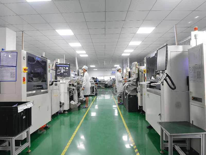
Panel Spacing Between Boards
The gap between adjacent boards has to accommodate the separation process, the routing or scoring allowance and the handling that follows. A gap that is too small leaves no room for the router bit or for the break, while a large gap consumes material that could have been used for boards.
The spacing should be chosen with the separation method in mind, because a scored panel and a routed panel have different requirements. The tolerance between the boards also affects the registration of the assembly process, since the position of each board within the panel determines where the paste and the components end up. A panel whose board positions drift within the panel will produce a placement error that the fiducials cannot fully correct.
<img src="https://www.gopcba.com/wp-content/uploads/2024/09/d72fc51735905611378fa8e31dee527-1536×1152-2.webp" alt="Breakaway tab detail on a panelised circuit board” />
Fiducials and Their Placement
Fiducials are the marks that the placement machine uses to find the panel, and their placement determines how accurately the machine can correct for the position of each individual board. Global fiducials locate the panel, while local fiducials locate a single fine pitch component or a board within the panel.
They need clear space around them, they must have a contrast that the vision system can detect and they must not be placed where a component or a rail can obscure them. Their position should be defined with a tolerance, and they should be the same on every panel of the same product, so that the machine program does not have to be re-taught for each delivery.
Breakaway Tabs and Perforations
Tabs are the small bridges of material that hold a board in the panel until it is separated. Their number, width and position determine how much stress the board sees during separation and how easily the board can be removed without damage, and they should be placed away from components and from traces that run to the edge.
Perforations, or mouse bites, allow the tab to break at a defined point, and they leave a small amount of material that has to be cleaned or accepted. The choice between tabs and a full score line depends on the board outline and on the assembly process, and the options are compared in the guide to breakaway tab design.
Strain Relief and Component Keep Out
Separation bends the board, and the bending produces a strain that travels through the laminate. Components close to the separation line see that strain directly, and a ceramic capacitor or a large package can crack even when the bend looks small. A keep out zone around the tab is the standard protection.
The keep out should cover the tab area and a margin that depends on the component and on the separation method. Where the design cannot avoid placing a component near the edge, the separation should be done with a tool that controls the force rather than by hand, and the risk should be acknowledged rather than ignored. The component type matters as well, since a ceramic part is more sensitive to bending than a plastic one.
Panel Size and Machine Limits
Every machine has a maximum and a minimum panel size, and the limits differ between the printer, the placement machines, the reflow oven and the inspection equipment. The panel has to satisfy all of them, and the smallest limit is the one that matters, not the largest.
The panel thickness and flatness also matter. A very thin panel may need a carrier or a stiffener to pass through the printer, and a thick panel may exceed the weight limit of a conveyor. Those constraints should be confirmed with the assembly house before the panel layout is finalised, because a change to the panel size after the stencil and the program have been prepared is expensive.
Material Utilization and Cost
The number of boards per panel affects the material cost, the handling cost and the yield. More boards per panel mean less waste and higher throughput, but also a larger panel that may exceed a machine limit or produce a heavier load on the conveyor.
The calculation should include the rails, the gaps, the fiducial areas and any coupon that the customer requires, because all of them consume material. The balance between utilisation and machine compatibility is one of the practical subjects covered in the guide to design and manufacturing cost reduction.
Documentation and Fabrication Notes
The panel drawing should show the panel outline, the board positions, the rail width, the gap, the tab detail, the fiducial positions and the separation method. It should also state which features are tooling only and will be discarded, so that the fabricator and the assembly house work from the same understanding of which dimensions are functional and which exist only to serve the process.
Those details belong in the fabrication notes, and the checks that should be completed before release are set out in the guide to the PCB production process flow. A panel drawing that leaves the rail width or the gap as an assumption will be interpreted differently by every supplier in the chain.
FAQ
How wide should a panel rail be? The value comes from the assembly equipment, since the conveyor and the clamps have to grip it reliably. Most lines use a rail of a few millimetres, and the exact figure should be confirmed with the assembly house before the panel is designed.
How much space should be left between boards? Enough for the separation method and for the tooling that supports the panel. A routed panel needs room for the cutter, a scored panel needs less, and the tolerance of the separation process should be added to the gap rather than assumed.
Can components be placed next to a breakaway tab? They can, but the risk of cracking during separation has to be assessed. A keep out zone around the tab is the usual answer, and where that is impossible the separation should be done with a controlled tool rather than by hand.