Power Sequencing Design for PCB Boards
Power sequencing is the question of which supply rail comes up first, how fast it rises and how the rest of the board behaves while it does. On a simple board with a single rail the question does not arise, and on a board with several rails feeding a processor, a memory, an analogue section and an interface it decides whether the board starts reliably or fails intermittently at power-up. The failures are difficult to diagnose precisely because everything works once the board is running.
Why Sequencing Is Required
Integrated circuits often specify a required power-up order, and the requirement is not arbitrary. Feeding a rail before its companion can forward bias internal junctions and cause a latch-up or an excessive current through a parasitic path. Some devices also require a specific relationship between the core and the input and output rails, and violating it can damage the part even though the board appears to work.
The requirement is usually stated as a maximum difference between rails during power-up and power-down, or as a maximum time between the rails reaching their operating values. Both matter, and the power-down case is the one most often forgotten. A board that is switched off with the rails collapsing in the wrong order can be damaged in the same way as one that is switched on in the wrong order.
Where the datasheet allows any order, the design still has to consider what the rest of the board does during the transition. Inputs that are driven before their supply is present will forward bias protection diodes and draw current through the driving device, which is a sequencing problem even though no individual part prohibits it.
Planning the Power-Up Order
Planning begins with a table of the supply rails, their voltages, their current requirements and the sequencing constraints of the devices they feed. The table usually reveals a natural order, typically the core supply, then the input and output rails, then the interfaces, and it also reveals the rails that must not precede others.
From the table, the enable signals can be arranged. The simplest approach is a chain, where a power good signal from one regulator enables the next, and it is adequate for most designs because it is self-timing. Timed delays are easier to analyse but depend on the tolerance of the timing components, and they can produce the wrong result if a rail is slow to rise.
The chain approach has to account for the behaviour of each regulator during its own start-up. A regulator that takes several milliseconds to reach regulation will delay everything after it, which is usually harmless, while a regulator that fails to assert its power good signal will hold the whole sequence. That failure mode should be considered deliberately, because it can leave the board in a state that is difficult to diagnose.
Inrush Current and Soft Start
Every rail draws a surge of current when it is first energised, because the output capacitors must be charged. The magnitude depends on the capacitance, the voltage and the impedance of the source, and the duration is short. A board with a large amount of bulk capacitance on several rails can present a surge that trips a supply, resets a regulator or blows a fuse that is correctly rated for the steady state current.
Soft start circuits limit the rate of rise so that the surge is spread over a longer period and the peak current is reduced. Many regulators include a programmable soft start, and where they do not, a series element or a controlled slew rate can be added. The trade is a slower power-up, which is rarely a problem.
The other inrush consideration is the order of charging. If several rails are enabled simultaneously, their surges add. Sequencing the rails so that only one is charging at a time reduces the peak demand on the upstream supply, which is often the reason a design passes its power-up test in the laboratory and fails in a system with a shared supply.
Reset Timing
Reset timing has to hold the processor in reset until every rail it depends on is stable and until the clock is running. The reset supervisor monitors one or more rails and releases the processor after a delay that is long enough for the supplies and the oscillator to settle. Too short and the processor starts before its supply is valid; too long is harmless.
The supervisor should monitor the rails that matter rather than only the main one. A processor whose input and output rail is late will start correctly and then misbehave when the rail arrives if the reset has already been released. Monitoring the last rail to stabilise, or combining the power good signals, is the usual answer.
Brown-out behaviour belongs to the same subject. If a rail dips below the operating minimum without going all the way down, the processor can execute unpredictable instructions unless the supervisor asserts a reset. Designing the supervisor to catch a brown-out condition is a small addition that removes a class of field failures which are otherwise impossible to explain.
Power-Down Behaviour
Power-down deserves the same analysis as power-up. When the input supply is removed, the rails collapse at rates determined by their loads and their capacitances, and the resulting order is often the reverse of the intended one but is not guaranteed to be. A rail with a light load may discharge slowly and hold a device in a partially powered state while its neighbours are already off.
Active discharge circuits or a controlled shutdown sequence can impose the required order. Where the processor can be asked to shut down before the supply is removed, a controlled sequence is straightforward. Where the supply is simply cut, the discharge paths have to be designed, and a small bleeder resistor on a lightly loaded rail is often enough.
The behaviour during a short interruption is the worst case. A brief loss of input power that does not fully discharge the rails can leave the board in an intermediate state from which it does not recover, and the symptom is a board that appears to have failed and then works after being switched off and on again. A supervisor that holds the reset until the rails are fully discharged removes the symptom.
Verification
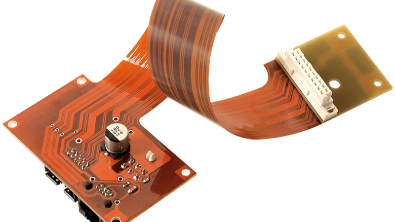
Verification is done at power-up with an oscilloscope rather than with a multimeter. The rise of each rail should be captured simultaneously, along with the reset signal and the clock, so that the relationships between them are visible. A capture of the full sequence usually reveals a timing margin that was assumed rather than verified.
The test should be repeated at the extremes of temperature and supply tolerance, and with the board under its maximum and minimum load. Regulators change their behaviour with load, and a sequence that is correct at room temperature with a nominal supply may not be at the cold corner with a low input voltage. These are the conditions under which the intermittent failures occur.
Repeated switching should be part of the test as well. A board that starts correctly once may fail at the twentieth attempt, and a power cycle loop with an automated check is the most efficient way to find it. This is particularly important where the design relies on a delayed sequence rather than on the regulators’ own power good signals.
Practical Rules
List the rails and their sequencing constraints, use the regulators’ own power good signals where possible, and provide soft start for any rail with significant bulk capacitance. Monitor the last rail to stabilise before releasing reset.
Verify power-up and power-down at the extremes with a simultaneous capture, and repeat the cycle many times. Record the sequence and its assumptions with the design and production records, because a power sequencing issue discovered in the field is far more expensive than one found on the bench, and the test data from the first build is what shows whether the margin was adequate.
FAQ
Why do supplies need a specific order? Because feeding one rail before another can forward bias internal junctions, cause latch-up or damage a device. Many datasheets specify a maximum difference between rails.
What is inrush current? The surge drawn when the output capacitors charge at power-up. It can trip a supply or blow a correctly rated fuse if it is not limited.
How should sequencing be verified? With a simultaneous oscilloscope capture of all rails, reset and clock, repeated at temperature and supply extremes and over many power cycles.