Thermal Pad Soldering with Solder Preforms
A thermal pad carries heat as well as current, and both depend on the joint beneath it having a large contact area and few voids. The joint is larger than any other on the board, which is why it is handled differently.
Why the Joint Voids
A large molten volume traps flux vapour beneath the component because there is no easy path for the gas to escape. The vapour collects into voids that reduce the contact area without changing the appearance of the joint.
The escape route is set by the pad geometry. Our voiding notes describe the limits that apply.
Setting the Volume
The volume has to fill the gap and leave a fillet without flooding the surrounding area. A stencil aperture that works for a normal pad deposits far too little for a thermal pad.
Where the volume is added by a preform, the preform thickness and area set the total. Our paste volume notes describe the measurement that goes with it.
<img src="https://www.gopcba.com/wp-content/uploads/2024/09/Gopcba_画板-1-副本.png" alt="Solder preform placed on a thermal pad” />
Solder Preform Selection
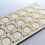
A preform is a shaped piece of solder that is placed on the pad before the component. It adds volume without adding flux, which is the reason it reduces voiding compared with extra paste.
The preform has to match the pad footprint and it has to be placed within the pad outline. Our placement notes describe the tolerance that applies.
Profile for a Large Joint
A large joint needs a longer soak so that the whole mass reaches temperature together, and a slower cooling so that the joint does not crack. The rest of the board wants a shorter profile, and the two have to be reconciled.
A soak that is long enough to flux the largest pad is the usual compromise. Our soak profile notes describe the effect on voids.
Ground Plane Effects
A thermal pad usually connects to an internal plane, and the plane conducts heat away during reflow. The pad therefore reaches temperature later than the rest of the board, which shifts the profile locally.
The plane should be considered when the profile is set rather than afterwards. Our thermal design notes describe the connection.
Inspection and Acceptance
X-ray is the practical inspection, because the joint is under the component. The void percentage is read against a limit that is stated for the product rather than adopted from a standard.
A pad with distributed small voids behaves differently from one with a single large void, and the criterion should say which is acceptable. Our X-ray notes describe the reading.
Verification
The verification is a preform placed within the pad outline, a profile recorded at the thermal pad itself, and a void measurement taken after the first article and after any change of paste, preform or profile.
Our first pass yield notes describe how the records are used.
Process Control and Verification
On a design of this kind, thermal pad is the item that decides how the rest of the board is arranged. Reviewing the design before the data is released is cheaper than correcting it after the panel is in the tank, because every step downstream inherits the decision made at the front end. Documenting the assumption is part of the design work, and a short note on the drawing prevents a question that would otherwise arrive a day later and cost a day of schedule.
The process window is set by the narrowest step in the flow, so an improvement anywhere else shows up as margin rather than as yield until that step is addressed. A short note on the drawing about handling, storage or packaging is often worth more than an extra decimal place on a tolerance.
Where a value sits close to a process limit, the drawing should say so, since the shop can then open the process window rather than working to a nominal figure that carries no tolerance. A stack-up that is drawn rather than described removes most of the ambiguity from a quotation, and it lets the fabricator price the board against the dielectric and copper weights that will actually be used.
Where the requirement is not written down, the shop supplies its own default, and the default is chosen for the process rather than for the design. The measurements that matter are the repeatable ones: conductor width and spacing, annular ring, finished hole size, plating thickness and surface finish are all verifiable on a coupon that travels with the panel.
Running a first article through the same checks as the production panel confirms that the two agree, and that comparison is the cheapest form of process control available at prototype stage.
Process Control and Verification
On a design of this kind, thermal pad is the item that decides how the rest of the board is arranged. Reviewing the design before the data is released is cheaper than correcting it after the panel is in the tank, because every step downstream inherits the decision made at the front end. Documenting the assumption is part of the design work, and a short note on the drawing prevents a question that would otherwise arrive a day later and cost a day of schedule.
The process window is set by the narrowest step in the flow, so an improvement anywhere else shows up as margin rather than as yield until that step is addressed. A short note on the drawing about handling, storage or packaging is often worth more than an extra decimal place on a tolerance.
Where a value sits close to a process limit, the drawing should say so, since the shop can then open the process window rather than working to a nominal figure that carries no tolerance.
Process Control and Verification
On a design of this kind, thermal pad is the item that decides how the rest of the board is arranged. Reviewing the design before the data is released is cheaper than correcting it after the panel is in the tank, because every step downstream inherits the decision made at the front end. Documenting the assumption is part of the design work, and a short note on the drawing prevents a question that would otherwise arrive a day later and cost a day of schedule.
The process window is set by the narrowest step in the flow, so an improvement anywhere else shows up as margin rather than as yield until that step is addressed.
Process Control and Verification
On a design of this kind, thermal pad is the item that decides how the rest of the board is arranged. Reviewing the design before the data is released is cheaper than correcting it after the panel is in the tank, because every step downstream inherits the decision made at the front end. Documenting the assumption is part of the design work, and a short note on the drawing prevents a question that would otherwise arrive a day later and cost a day of schedule.
A first article check confirms that the process and the drawing agree on the points listed above, and that the coupon data supports the values used in the design.
Where a measurement falls outside the expected window, the sample is retained so that the cause can be established before the balance of the batch is released.
FAQ
Can paste alone be used? It can, but the volume needed for a large pad means a thick deposit and a lot of flux, and the flux is what becomes vapour under the component.
Does a preform need its own flux? Usually the paste printed on the pad supplies it. Where it does not, a flux coated preform is used and the residue has to be cleanable.
What does gopcb provide for thermal pad assembly? We provide a volume calculated from the gap and the fillet, a preform sized to the pad footprint, a profile measured at the thermal pad rather than at a test point elsewhere, and a void reading taken against a stated limit for the product.