Test Fixture Design for Board Assembly
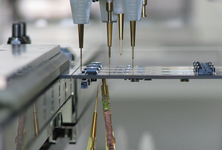
A test fixture is a mechanical and electrical interface between the product and the tester, and its design decides how much of the board can be tested and how repeatable the result is. A fixture that is built from the netlist alone usually performs worse than one that was designed with the layout.
The design work is in the details: probe selection, wiring, grounding, mechanical support and the maintenance that keeps the measurement valid over thousands of cycles.
Probe Selection
Probes differ in travel, spring force, tip style and current rating, and the choice follows from the pad size, the board support and the signal. A probe with too much force damages a small pad, while one with too little does not penetrate the oxide.
The tip style matters for the same reason: a sharp tip penetrates a coating, while a flat tip is used on a pad that must not be marked. The selection should be documented per product.
Wiring and Signal Integrity
The wiring between the probe and the tester is part of the measurement circuit, and its length and routing affect the result. Long wires add inductance and pick up noise, which is why a ground plane is used in the fixture itself.
For a high frequency measurement, the wiring should be treated as a transmission line and the return path kept close. This is the same concern that applies to the board, as discussed in impedance analysis.
Crosstalk Between Probes
Probes are close together by necessity, so capacitive and inductive coupling between them is unavoidable and must be managed. Separating the sensitive nets onto different probe modules and grounding between them are the standard measures.
Where crosstalk cannot be removed, the measurement limits have to account for it, and the test programme should be validated against a known good board.
Mechanical Support and Alignment
The fixture has to hold the board flat and align it to the probes, which requires support posts under the board and a locating feature such as tooling pins. Without support, the board flexes and the probes on the centre of the board may not contact.
The alignment features should use the tooling holes defined by the design, and the fixture should be built to those dimensions rather than to the outline.
Contact Pressure and Board Flex
The total force is the sum of the individual probe forces, which on a dense board can be substantial. The support must be placed where the board is stiff, and the flexure should be predicted rather than discovered.
Where the board is thin or the probe count is high, a support plate with a compliant layer distributes the load and protects the surface.
Grounding and Shielding
The fixture should have a solid ground plane connected to the tester, and the board ground should be bonded to it at several points. This reduces noise and provides a defined return for every measurement.
Where the measurement is sensitive, the fixture can be enclosed in a shield that is bonded to the same ground, which also reduces the effect of nearby equipment.
Maintenance and Wear
Probes wear, springs weaken and contacts oxidise, so the fixture has a life that is measured in cycles. The maintenance schedule should include a probe replacement interval and a periodic verification with a known good board.
The verification board should be retained with the fixture, and its result recorded so that a change in the measurements can be attributed to the fixture or to the product.
Fixture Cost and Volume
A fixture has a tooling cost and a lead time, so it is justified by the volume and by the test time it saves. For a small batch a flying probe is usually cheaper overall, as described in the comparison of flying probe and fixture test.
Where the product will run for years, the fixture should be ordered early, since its lead time can exceed the board lead time.
Documentation
The fixture documentation should include the probe list, the wiring schedule, the support positions, the alignment features and the maintenance plan. It should be revision controlled with the product.
A fixture that is not maintained with the product will drift out of step with it, and the first sign is usually a test that starts failing boards that are good.
Process Control and Verification
On a design of this kind, board support is the item that decides how the rest of the board is arranged. Documenting the assumption is part of the design work, and a short note on the drawing prevents a question that would otherwise arrive a day later and cost a day of schedule. The process window is set by the narrowest step in the flow, so an improvement anywhere else shows up as margin rather than as yield until that step is addressed.
A short note on the drawing about handling, storage or packaging is often worth more than an extra decimal place on a tolerance. Where a value sits close to a process limit, the drawing should say so, since the shop can then open the process window rather than working to a nominal figure that carries no tolerance.
A stack-up that is drawn rather than described removes most of the ambiguity from a quotation, and it lets the fabricator price the board against the dielectric and copper weights that will actually be used. Where the requirement is not written down, the shop supplies its own default, and the default is chosen for the process rather than for the design.
Related reading: our fabrication notes, board quality and design release notes cover the same ground.
Process Control and Verification
On a design of this kind, board support is the item that decides how the rest of the board is arranged. Documenting the assumption is part of the design work, and a short note on the drawing prevents a question that would otherwise arrive a day later and cost a day of schedule. The process window is set by the narrowest step in the flow, so an improvement anywhere else shows up as margin rather than as yield until that step is addressed.
A short note on the drawing about handling, storage or packaging is often worth more than an extra decimal place on a tolerance.
Process Control and Verification
On a design of this kind, board support is the item that decides how the rest of the board is arranged. Documenting the assumption is part of the design work, and a short note on the drawing prevents a question that would otherwise arrive a day later and cost a day of schedule. The process window is set by the narrowest step in the flow, so an improvement anywhere else shows up as margin rather than as yield until that step is addressed.
A first article check confirms that the process and the drawing agree on the points listed above, and that the coupon data supports the values used in the design.

Where a measurement falls outside the expected window, the sample is retained so that the cause can be established before the balance of the batch is released.
A first article check confirms that the process and the drawing agree on the points listed above, and that the coupon data supports the values used in the design.
Where a measurement falls outside the expected window, the sample is retained so that the cause can be established before the balance of the batch is released.
FAQ
How many probes can a fixture carry? As many as the grid and the support allow, and the practical limit is usually the total contact force rather than the probe count.
Do fixtures need periodic verification? Yes, with a known good board and a recorded result, because probe wear changes the measurement over time.
Can a fixture test high frequency signals? It can with careful wiring and grounding, and the fixture becomes part of the measurement circuit.
When is a flying probe the better choice? For a low volume product or one that will change before the fixture is amortised.