
Shield Can Attachment and Removal
A shield can is a metal cover that reduces the electromagnetic field leaving or entering a circuit, and it works only if it is connected to the ground reference at many points. The attachment is therefore electrical as much as mechanical.
The can is usually soldered to a ring of pads around the circuit, and the quality of those joints determines the shielding effectiveness. A can that is attached at four corners and nowhere else does little.
What the Shield Has to Achieve
The shielding effectiveness depends on the material, the thickness and, most importantly, on the continuity of the ground connection and the size of any aperture. A seam or a hole that is a significant fraction of a wavelength allows the field through.
The requirement should be stated as a target rather than as a general instruction, because a can that is intended to reduce emissions differs from one that protects a sensitive circuit from an external field.
Shield Frames and One Piece Cans
A two piece arrangement uses a frame that is soldered to the board and a lid that clips onto it, which allows access for inspection and rework. A one piece can is soldered directly and must be removed to reach the circuit.
The choice affects the assembly process, the rework strategy and the height profile. It should be made with the service requirement in mind rather than with the assembly cost alone.
Ground Pads and Stitching
The pads around the perimeter should be numerous and evenly spaced, and each should be connected to the ground plane by vias rather than by a long trace. A pad that is connected by a trace has inductance that limits the shielding at high frequency.
The via pattern should be dense enough that the gaps between the vias are small compared with the wavelength of interest, which is the same reasoning that applies to grounding design.
Paste Volume and Joint Formation
The joint has to form on the wall of the can and on the pad, and that requires enough paste to fill the corner without creating a bridge to a neighbouring feature. The aperture is usually a slot along the pad rather than a simple rectangle.
Too little paste and the can is not sealed, while too much creates a fillet that can interfere with the lid or with a neighbouring component. The volume should be established with a first article rather than by eye.
Placement and Coplanarity
A shield can is a large thin part, and its flatness determines whether all of the pads are contacted at the same time. A can that is twisted touches some pads and not others.
The placement force and the nozzle should be chosen for the part, and the coplanarity should be checked on a sample from each lot. A can that is distorted after reflow is a sign of a thermal gradient across the part.
Cleaning and Residue Under the Can
Flux residue under a shield is trapped, and if the can is sealed the residue cannot be removed afterwards. Where cleaning is required, the can should be fitted after the cleaning step, which usually means a two piece design.
Where a one piece can is used, the flux should be qualified as no clean and the residue assessed for the environment. This is the same assessment described for no clean residue risk.
Removal for Rework
Removing a soldered can requires heating all of the joints without damaging the components inside, which is difficult because the can shields the heat as well as the field. A hot air nozzle from above may heat the can faster than the joints.
Where rework is expected, the two piece design is strongly preferred, since the lid can be removed without touching the solder joints. The repair of the circuit then leaves the frame and its joints intact.
Inspection
Inspection of the joints is visual where the can does not cover them, and by X-ray or by a pull test where it does. A pull test on a sample is the practical verification that the attachment is mechanically adequate.
The electrical verification is a continuity measurement between the can and the ground plane, which should be made on a sample or on every board where the requirement is critical.
Documentation
The drawing should state the can, the frame, the pad pattern, the paste aperture and the ground via pattern, together with the shielding target. It should also state the order of operations relative to cleaning and coating.
Where the can is fitted after a coating step, the coating must be excluded from the ground pads, which is a masking requirement that belongs in the same document. These items appear in the design release review on any product with shielding.
Additional Considerations for This Build
Practical attention to rework access pays for itself here, because it decides whether the finished board behaves as the drawing intended. Where the requirement is not stated on the fabrication drawing or in the assembly notes, the shop has to assume a default, and that default is rarely the value the design was simulated with. Stating rework access explicitly, together with the tolerance that applies, removes the assumption and keeps the result predictable from batch to batch.
Process Control and Verification
On a design of this kind, paste volume is the item that decides how the rest of the board is arranged. Where a value sits close to a process limit, the drawing should say so, since the shop can then open the process window rather than working to a nominal figure that carries no tolerance. A stack-up that is drawn rather than described removes most of the ambiguity from a quotation, and it lets the fabricator price the board against the dielectric and copper weights that will actually be used.
Where the requirement is not written down, the shop supplies its own default, and the default is chosen for the process rather than for the design. The measurements that matter are the repeatable ones: conductor width and spacing, annular ring, finished hole size, plating thickness and surface finish are all verifiable on a coupon that travels with the panel.
Running a first article through the same checks as the production panel confirms that the two agree, and that comparison is the cheapest form of process control available at prototype stage.
Process Control and Verification
On a design of this kind, paste volume is the item that decides how the rest of the board is arranged. Where a value sits close to a process limit, the drawing should say so, since the shop can then open the process window rather than working to a nominal figure that carries no tolerance. A stack-up that is drawn rather than described removes most of the ambiguity from a quotation, and it lets the fabricator price the board against the dielectric and copper weights that will actually be used.
A first article check confirms that the process and the drawing agree on the points listed above, and that the coupon data supports the values used in the design.
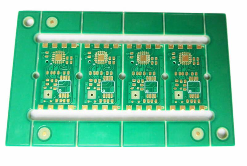
Where a measurement falls outside the expected window, the sample is retained so that the cause can be established before the balance of the batch is released.
A first article check confirms that the process and the drawing agree on the points listed above, and that the coupon data supports the values used in the design.
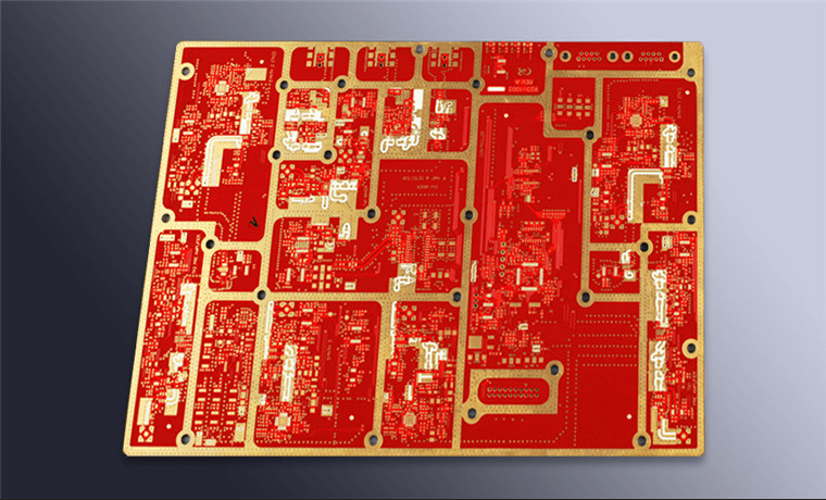
Where a measurement falls outside the expected window, the sample is retained so that the cause can be established before the balance of the batch is released.
FAQ
Does a shield can need to be grounded at every pad? It needs a continuous ground connection, which in practice means many evenly spaced pads rather than a few.
Can a can be attached with adhesive? It can for a mechanical cover, and an adhesive connection does not provide a reliable ground for shielding.
Should the can be fitted before or after cleaning? After, where cleaning is required, so that the residue under the can can be removed.
What limits the shielding effectiveness? Usually the apertures and the seam continuity rather than the material thickness.