Solder Preforms in High-Power Assemblies
Solder paste is a convenient way to deliver alloy, but it is mostly flux by volume once the volatile fraction has boiled away. On a heavy copper joint the paste can supply far less metal than the joint needs, and the voiding that results is what limits thermal performance. A solder preform solves the problem by delivering a known, solid volume of alloy to a specific place. This article explains when a preform is the right answer, how it is combined with paste, and how the joint is profiled and checked.
What a Solder Preform Is
A solder preform is a piece of alloy shaped to fit a joint: a washer, a ring, a rectangle, a disc or a custom outline stamped or cut to match a footprint. It arrives with a defined thickness and a defined alloy, so the volume of metal it contains is a fixed number rather than a variable that depends on print quality.
Preforms are usually supplied clean, and many carry a flux coating so that they can be placed by machine. Because they are solid they do not dry out, do not change viscosity with age and are unaffected by the humidity that degrades paste. Those properties make them attractive wherever repeatability matters more than convenience.
Why Volume Matters in Power Joints
The thermal path from a power die to a heatsink passes through the solder joint, and that joint is usually the largest thermal resistance in the path after the die itself. A joint that is thin because the paste deposit was small has a higher resistance, and voids remove conducting area altogether. Both effects raise the junction temperature for a given load.
Heavy copper makes the problem worse because the copper draws heat away during soldering, so the alloy may not fully coalesce before it freezes. The result is a joint with a rough internal structure and a scattered void pattern. Adding metal volume through a preform gives the alloy enough material to collapse into a continuous layer despite the thermal load.
Void Rate and Thermal Performance
Void rate is the fraction of the joint area that contains no solder, measured by X-ray or by scanning acoustic microscopy. For power devices the accepted limit is often ten per cent in total, with no single void larger than a defined size, because a large void directly under the die creates a hot spot that dominates the thermal behaviour of the whole package.
Preforms reduce void rate for two reasons. They supply the volume that lets the joint fill completely, and their solid form displaces flux rather than generating it. Flux is the main source of trapped volatiles, so delivering more metal with less flux is the most direct route to a low void count. Venting paths and a profile that lets the flux escape complete the picture.
Combining Paste with a Preform
In practice the preform is usually tacked in place with paste. A thin print holds the preform during handling and supplies the flux that cleans the surfaces and promotes wetting. The paste itself contributes little metal to the final joint; its job is to keep the preform where it was placed and to make the surfaces solderable.
Getting the ratio right matters. Too much paste leaves a thick flux residue that cannot escape and generates voids, while too little paste lets the preform move during transport or reflow. A common starting point is a print of a few tens of micrometres around the perimeter of the preform footprint, adjusted after the first cross section shows how the joint filled.
Preform Forms and Alloys
Alloy selection follows the thermal requirements of the assembly rather than convention. A high tin lead-free alloy suits most power work, while alloys with a higher melting point are chosen when the joint will operate hot or when a later reflow step must not remelt it. The alloy also determines the mechanical behaviour of the joint under thermal cycling.
Form follows function. A ring around a die attach site keeps alloy at the perimeter so that the centre is fed as it collapses. A washer under a screw terminal fills the annular gap. Custom shapes stamped to the outline of a footprint are common for large packages because they let the same placement equipment handle the preform as a component.
Placement and Fixturing
Preforms can be placed by hand, by a pick and place machine with a suitable nozzle, or by a dedicated dispenser. Machine placement is preferred wherever volume justifies it, because the preform has to sit within a fraction of a millimetre of the intended position; a shift of half a millimetre on a small die attach site moves enough alloy to create an unbalanced joint.
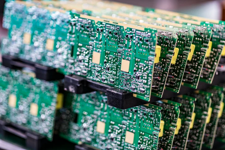
Fixturing keeps the preform in place between placement and reflow. A shallow pocket in a graphite or aluminium carrier holds the part and the preform together, and the carrier also protects the assembly while it moves. Where a single board carries several heavy joints, a carrier that locates all of them at once removes most of the handling risk.
Profiling for a Preform Joint
A preform joint needs a profile that gives the flux time to act and the alloy time to collapse. A slow ramp with a soak near the activation temperature lets the flux clean the surfaces and boil away before the alloy melts, which is exactly what a low void count requires. Rushing the ramp traps volatiles under the molten metal and creates the voids the preform was meant to eliminate.
The peak must also be long enough for the whole joint to reach liquidus, and that depends on the copper beneath it. A thermocouple attached to the actual joint, not to the carrier, is the only way to confirm the peak. Where a heavy copper plane supports the joint, the dwell above liquidus often needs to be extended well beyond what a standard profile allows.
Quality Control
Inspection combines X-ray for void rate with cross sectioning for a small sample of joints. X-ray gives a fast picture of the whole population, while a section shows the bond line thickness, the grain structure and whether the preform melted completely. A joint that looks acceptable on X-ray can still have a thick, uncoalesced core.
The thermal design that the joint serves should be checked at the same time. Our notes on heavy current capacity and on thermal management design explain how the joint fits into the wider path, and a metal core or ceramic substrate changes the calculation as described in metal core versus ceramic boards.
FAQ
Can a preform replace paste entirely? On some joints it can, provided the surfaces are pre-fluxed and the preform is held in place mechanically. Most production processes still use a thin paste print because it simplifies placement and supplies flux.
How thick should a preform be? Thickness is set by the alloy volume the joint needs, which is the joint area multiplied by the intended bond line. It is a design calculation, not a rule of thumb, and it should be confirmed by cross section on the first build.
Does a preform guarantee a void free joint? No. It removes the volume shortage and reduces the flux load, but voids still form if the profile is too fast or the surfaces are contaminated. Venting and profile control remain essential.