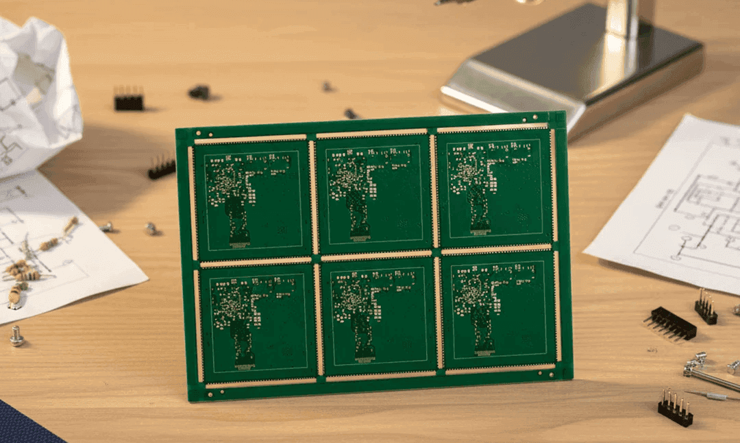
Flex Core Thickness and Bend Radius in a Rigid Flex Build
A rigid flex stackup is arranged around the bend rather than around the routing. The layers that cross the bend area have to be symmetrical about a neutral axis, the copper in that area has to be thin and covered, and the adhesive has to stop before the bend so that the flexible region stays flexible. Getting the arrangement right at the start is far cheaper than discovering the problem after the first fold test.
The Role of the Neutral Axis
When a flexible section bends, the material on the inside of the curve is compressed and the material on the outside is stretched. Between them there is a surface that does neither, and it is called the neutral axis.
A conductor placed at the neutral axis sees almost no strain. A conductor placed away from it sees strain proportional to its distance from the axis and to the bend radius, which is why the arrangement of the layers is a mechanical decision and not only an electrical one.
A single conductive layer in a flex is automatically at the neutral axis, because there is nothing on the other side of it. As soon as a second layer is added, the pair must be placed symmetrically or one of them will be strained more than the other.
Arranging the Layers
A balanced construction places equal thicknesses of material on each side of the conductive layers. An unbalanced stack curls as the adhesive cures and again when the board is heated, and a curled flex does not lie flat in a fixture.
The number of layers in the flex core should be kept to the minimum the routing requires. One layer bends easily, two layers bend to a larger radius and beyond that the assembly is normally treated as a flex with rigidised areas.
The rigid layers are added on the outside of the areas that must stay stiff, and they should be arranged so that the stack is also balanced in the rigid region. A rigid area with more layers on one side of the flexible core will bow when it is laminated and again during reflow.

The Bend Area
The bend area should contain only the flexible core, its copper and its coverlay. Any rigid material, any adhesive that has flowed into the region and any plating that has reached it will change the mechanical behaviour.
The coverlay has to be bonded over its full area, because an unbonded coverlay behaves as a separate layer and takes the strain in a way the design did not intend. The bond line should extend into the rigid area, where it can be anchored under the rigid layers.
The copper in the bend area should be thin and should run perpendicular to the bend line. A trace that runs along the bend direction is strained over its whole length, while one that crosses at a right angle is strained over a narrow strip.
Adhesive Selection and Flow
The adhesive holds the stack together and its flow has to be controlled. It must fill the cavities between the layers without voids, and it must not reach the bend area where it would stiffen the flex.
Adhesive free constructions build the copper directly on the polyimide and remove the flow problem entirely. They are thinner, they bend to a smaller radius and they avoid the outgassing that an acrylic adhesive produces during reflow.
The lamination cycle determines the flow. A slow ramp with a controlled pressure lets the adhesive move gradually, while a fast cycle drives it into places it should not reach. The cycle should be developed with a section of the finished panel as the evidence.
Copper Thickness and Plating
Thin copper bends better. A rolled annealed foil has a grain structure that resists cracking under repeated bending far better than an electrodeposited foil of the same thickness, and it is the usual choice for a dynamic flex.
Plating in the bend area should be avoided. The plating is brittle compared with the foil, and a plated through hole or a plated edge inside the bend is a crack initiation site. The design rule is to keep all plating a defined distance from the bend line.
Where a via must be placed near the bend, it should be on the rigid side of the transition and it should be supported by the rigid material. A via that sits in the flexible region may survive the assembly and fail after a few hundred folds.
Fabrication Sequence
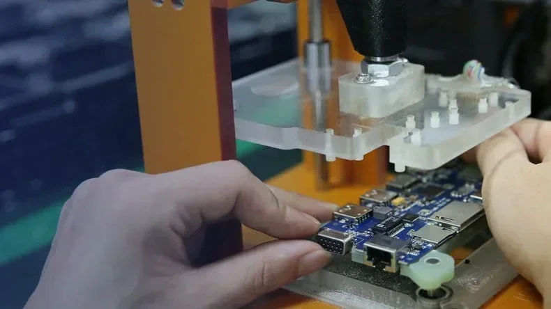
The sequence begins with the flexible core, which is imaged, etched and covered. The coverlay is laminated next, and the rigid layers are added on both sides in a second lamination.
The drilling and plating follow, and then the rigid material is removed from the flexible areas by controlled depth milling. The depth is set from a measurement of the laminated panel, because the nominal thickness of the stack does not describe the actual panel.
The final steps are the surface finish and the forming. A finish that requires a high temperature should not be applied to a flex that has already been formed, and the forming should be done with a fixture that sets the radius rather than by hand. The fixture should be checked against the drawing before the first production panel is folded.
Verification
The bend radius should be verified on a sample by folding it to the design minimum and examining the copper for cracks. A section after the fold shows whether the layers remained in position and whether the adhesive reached the bend. A fold carried out by hand is not a measurement, and a fixture that sets the radius is what makes the result repeatable.
The thermal cycling test is the one that reveals the balance of the stack. An unbalanced construction curls and the plated holes in the transition region crack, and the failure appears after a number of cycles rather than at the first one.
The fabrication drawing should carry the stackup with the material and the thickness of each layer, the location of the bend areas, the radius and the coverlay. Without those, the fabricator will build a stack that meets the electrical requirement and not the mechanical one.
Practical Rules
Keep the bend area to the flexible core and the coverlay, place the conductors symmetrically about the neutral axis, and stop the adhesive before the bend. Use thin rolled foil and keep plating away from the fold.
Record the stackup and the bend data with the build records and the flex processing rules, and review the rigid flex manufacturing and the flexible material data when the construction is defined.
FAQ
Why does the stack have to be balanced? An unbalanced stack curls as the adhesive cures and again when heated. A flex that curls does not lie flat in a fixture and the plated holes in the transition are stressed.
Why keep plating out of the bend area? Plating is brittle compared with rolled foil. A plated hole inside the bend acts as a crack initiation site and fails after repeated folding.
Why roll the rigid material away rather than drill it? The flex has to be exposed without damaging the copper or the coverlay. Controlled depth milling, with the depth set from the actual panel thickness, is the standard method.