
Conformal Coating Thickness Measurement Methods
Conformal coating is applied to a defined thickness, and the thickness is the parameter that decides how long the coating protects. Measuring it on a curved assembly is harder than it sounds, and the method chosen decides what figure is being reported.
Why the Thickness Matters
The coating protects by presenting a barrier, and the barrier has to survive the same thermal cycling and mechanical handling as the assembly. A coating that is thinner than the specification has a shorter life, and one that is thicker can crack as it cures.
The thickness is therefore specified as a range rather than a minimum, which is unusual for an assembly requirement and is a consequence of the coating’s own mechanical limits. Our coating notes describe the application side of that.
Methods That Work on a Curved Surface
A micrometer on a flat coupon works and does not measure the product. A measurement on the product has to work on the edge of a component, in a shadow, and on a surface that may be vertical.
The methods that cope are the ones that are thickness specific: ultrasonic measurement through the coating, eddy current on a coated metal, and optical methods that resolve a cross section. Each reports a real thickness rather than an indication. Our coating inspection notes describe how coverage is verified separately.
A coating that contains a UV tracer can be inspected under ultraviolet light, which makes the coverage visible. That answers the question of where the coating is, and it does not answer how thick it is.
The two inspections are therefore complementary rather than alternatives. A board that is fully covered and thin will pass a UV check and fail its life requirement.

Coverage asks whether the coating reached the surfaces that need protection. Thickness asks whether there is enough of it. A board can be fully covered and thin at a shadowed point, and that point is where the failure will occur.
The measurement plan therefore names the locations rather than counting readings. The locations are the ones where the coating is thinnest, which are the edges of components and the areas where the flow was interrupted.
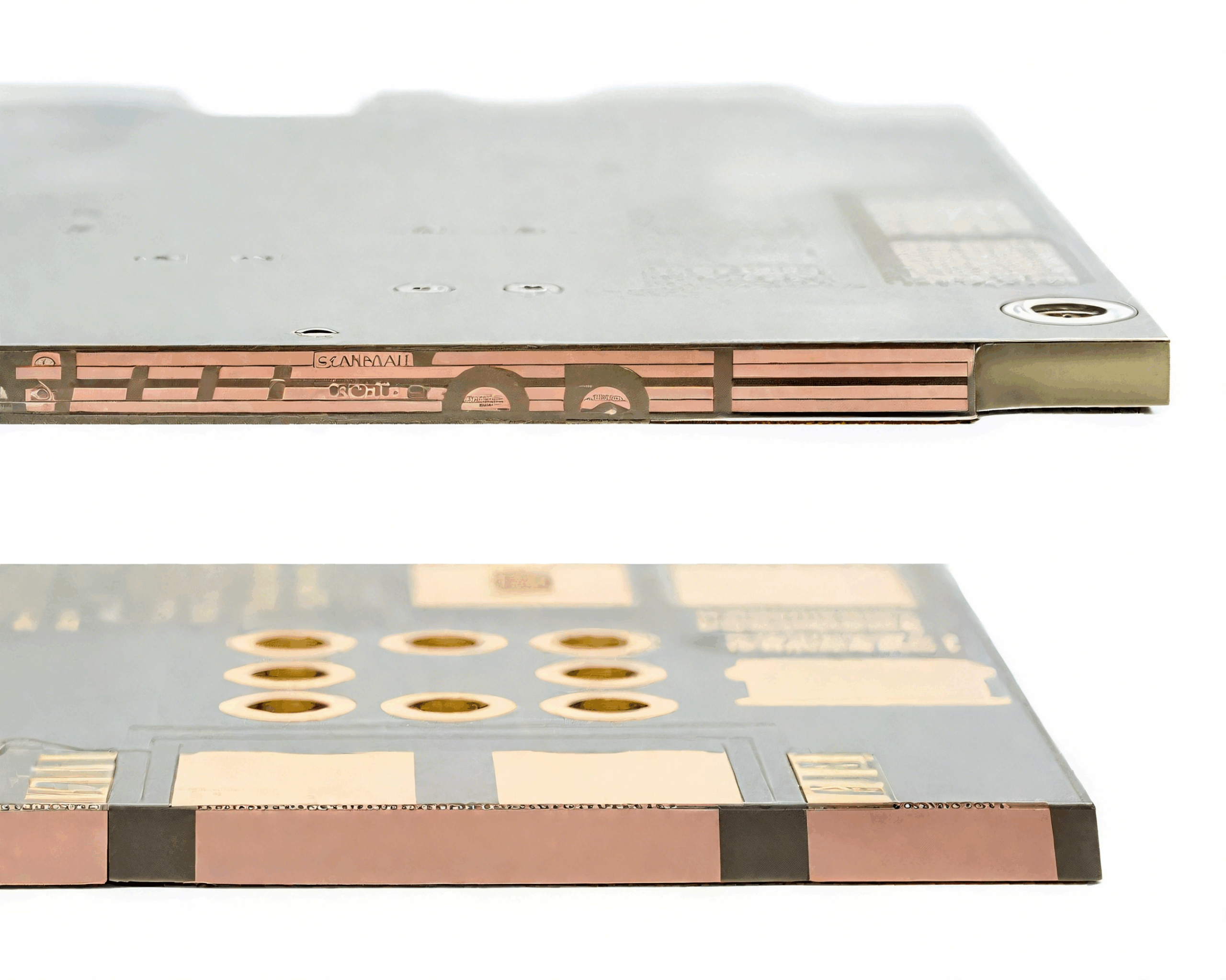
A cross section gives the true thickness and the true coverage at the same time, and it destroys the board. It is used on a sample or on a process monitor rather than on the product.
The monitor is worth more than a measurement on a product board because it can be cut at the same location on every batch, which makes the results comparable. Our board quality notes describe how the sample is selected.
The record that makes the process controllable is the thickness at the named locations, the coating material and lot, the application parameters and the coverage inspection result. With those four, a change in the result can be attributed.
The thickness at a single point is not enough to describe a coating process, because the distribution matters as much as the average. A board that meets the average and is thin at a component edge will fail there.
Process Control and Verification
On a design of this kind, coating thickness is the item that decides how the rest of the board is arranged. Reviewing the design before the data is released is cheaper than correcting it after the panel is in the tank, because every step downstream inherits the decision made at the front end. Documenting the assumption is part of the design work, and a short note on the drawing prevents a question that would otherwise arrive a day later and cost a day of schedule.
The process window is set by the narrowest step in the flow, so an improvement anywhere else shows up as margin rather than as yield until that step is addressed. A short note on the drawing about handling, storage or packaging is often worth more than an extra decimal place on a tolerance.
Where a value sits close to a process limit, the drawing should say so, since the shop can then open the process window rather than working to a nominal figure that carries no tolerance. A stack-up that is drawn rather than described removes most of the ambiguity from a quotation, and it lets the fabricator price the board against the dielectric and copper weights that will actually be used.
Where the requirement is not written down, the shop supplies its own default, and the default is chosen for the process rather than for the design. The measurements that matter are the repeatable ones: conductor width and spacing, annular ring, finished hole size, plating thickness and surface finish are all verifiable on a coupon that travels with the panel.
Process Control and Verification
On a design of this kind, coating thickness is the item that decides how the rest of the board is arranged. Reviewing the design before the data is released is cheaper than correcting it after the panel is in the tank, because every step downstream inherits the decision made at the front end. Documenting the assumption is part of the design work, and a short note on the drawing prevents a question that would otherwise arrive a day later and cost a day of schedule.
The process window is set by the narrowest step in the flow, so an improvement anywhere else shows up as margin rather than as yield until that step is addressed. A short note on the drawing about handling, storage or packaging is often worth more than an extra decimal place on a tolerance.
Where a value sits close to a process limit, the drawing should say so, since the shop can then open the process window rather than working to a nominal figure that carries no tolerance.
Process Control and Verification
On a design of this kind, coating thickness is the item that decides how the rest of the board is arranged. Reviewing the design before the data is released is cheaper than correcting it after the panel is in the tank, because every step downstream inherits the decision made at the front end. Documenting the assumption is part of the design work, and a short note on the drawing prevents a question that would otherwise arrive a day later and cost a day of schedule.
The process window is set by the narrowest step in the flow, so an improvement anywhere else shows up as margin rather than as yield until that step is addressed.
Process Control and Verification
On a design of this kind, coating thickness is the item that decides how the rest of the board is arranged. Reviewing the design before the data is released is cheaper than correcting it after the panel is in the tank, because every step downstream inherits the decision made at the front end. Documenting the assumption is part of the design work, and a short note on the drawing prevents a question that would otherwise arrive a day later and cost a day of schedule.
Can the thickness be measured after curing? It can, and the measurement is taken after cure because the coating shrinks as the solvent leaves.
Is a UV inspection enough? It answers the coverage question and not the thickness question, so the two are used together.
What does gopcb provide for coating thickness? We provide a thickness range specified from the material data, measurements taken at named locations where the coating is thinnest, non-destructive methods qualified against a cross section, coverage checked separately by UV, and records that tie the result to the material lot and the application parameters.