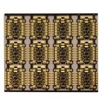
Non Solder Mask Defined vs Mask Defined Pads
Two pads of identical copper area can produce joints with very different reliability, and the difference is whether the solder mask opening is larger than the copper or smaller than it. A non solder mask defined pad exposes the whole copper feature and lets the mask sit back from it, while a mask defined pad covers the copper perimeter so that the opening, not the copper, sets the joint area. The choice changes the mechanics of every joint on the board.
The Two Constructions
In a non solder mask defined pad the mask opening is larger than the copper by a defined expansion, so the pad has a rim of exposed laminate or mask step around the metal. The solder wets the full copper area and forms a fillet around the edge of the metal, which is where the mechanical strength comes from.
In a mask defined pad the mask opening is smaller than the copper, so the mask overlaps the metal and defines where the paste and the solder can sit. The copper extends beyond the opening and is covered, which means the joint area is set by the artwork of the mask rather than by the copper pattern.
Registration and Tolerance
Mask defined pads are more tolerant of mask registration error, because a shift in the opening moves the joint area but does not expose unwanted copper. That is their main advantage, and it is why they remain common on fine pitch packages where the opening is small and the copper is larger than the joint needs to be.
Non solder mask defined pads are less forgiving of registration, because the expansion has to be maintained on every side. If the opening shifts far enough, one edge of the copper becomes covered and the fillet is truncated. The acceptable shift is therefore a real requirement, and it should be stated as a tolerance rather than assumed. Our note on solder mask opening tolerance covers how that value is established.

Joint Geometry and Strength
The strength of a solder joint comes largely from the fillet that forms around the perimeter of the pad. A non solder mask defined pad allows that fillet to form on all four sides, and the mask step behind it acts as a dam that stops the solder running away. The result is a joint that resists shear and thermal fatigue well.
A mask defined pad has no fillet at the covered edges. The joint is a column of solder confined within the opening rather than a filleted connection, which reduces the load bearing area and concentrates strain at the mask edge. For a package with many small joints, the cumulative effect on thermal fatigue life is significant.
Paste Deposition
Paste volume is set by the stencil aperture, and the aperture is normally matched to the mask opening for a mask defined pad and to the copper for a non solder mask defined pad. That difference changes the deposit that actually reaches the joint, because paste printed onto a mask step sits in a well while paste printed onto exposed copper sits flat.
The stencil and the mask therefore have to be designed together. A stencil sized for the copper on a mask defined pad over-prints, producing excess alloy and a greater bridging risk, and the reverse under-fills the joint. The relationship is the same one described in our article on paste volume and stencil design.
<img src="https://www.gopcba.com/wp-content/uploads/2026/08/5lRxYcI_XX3h4-BipULu61gw3L-RLFsml7hKUIgIa_VH27O-NxAY4kwXW-anx9eybam9Oi6IQU1Z6Ikty88PAv96DDaMknpa0qy0QqunYNmrcMEdlDPmwA9BhROsA1D9O822fX5pNp5xOnz-tn-6Lh4qo_E3y_iCy67kzO0tfMdAZvnqq2fkM1twbpuC3hx-1.jpg" alt="Solder mask opening offset over a copper pad seen from above” />
Assembly and Rework Effects
Self alignment during reflow depends on the surface tension of the molten fillet. A non solder mask defined pad gives the joint a symmetric pull towards the pad centre, which helps a component centre itself. A mask defined pad provides less of that pull at the covered edges, so placement accuracy has to carry more of the burden.
Rework is easier on a mask defined pad because the mask limits how far solder can spread, while a non solder mask defined pad gives more room for a wick or a vacuum tool. The trade is the same as in the original assembly: confinement versus fillet area.
Choosing by Package Type
Ball grid array and chip scale packages are normally designed with non solder mask defined pads because the fatigue life of the joints is the limiting factor and the fillet matters. Fine pitch quad flat packages and smaller discretes are often mask defined because the mask opening is small enough that registration dominates.
The decision also depends on the fabricator capability. A supplier that can hold a tight mask registration makes the non solder mask defined option safe, while one that cannot makes it risky. That capability should be established before the design is released rather than discovered on the first build, and the evidence used is the same kind of data described in our article on component tolerance and reliability.
Design Checklist
For a non solder mask defined pad, state the mask expansion on every side, confirm that the expansion can be held, and check that the mask step does not fall where a component body will sit. For a mask defined pad, state the opening size and its tolerance, confirm that the stencil aperture matches the opening rather than the copper, and check that the joint area is adequate for the load.
Either way, the rule should be applied consistently across the board. A mixture of the two constructions on one component footprint is a reliable way to produce a joint that is unpredictable, and the assembly notes should record which construction was intended where the two are used on the same board.
Checks Before Release
Where a decision is made by judgement, a boundary sample makes the judgement repeatable between operators and between shifts. Where a process is at the edge of its capability, the margin should be bought deliberately rather than discovered during production.
FAQ
Which is more reliable? For a package with many small joints, the non solder mask defined construction is generally more fatigue resistant because it allows a full fillet.
Why would anyone choose mask defined? Registration tolerance. Where the opening is very small, covering the copper perimeter prevents accidental exposure and keeps the joint area predictable.
Does the choice affect bridging? It can. A mask defined pad confines the alloy within the opening, which reduces bridging, while a non solder mask defined pad relies on the mask step and the correct paste volume to do the same.