Wire and Cable Assembly in Box Build
Wiring inside an enclosure is the part of assembly where a mistake is most expensive to find. A crimp that is not fully inserted, a wire routed over a sharp edge or a connector latched into the wrong position may pass an electrical test and fail after the product has been installed, when the harness has been flexed a few hundred times or the enclosure has been closed. The work is repetitive, and repetition is exactly where documentation and tooling matter most.

Crimping and Termination
A crimped connection relies on the deformation of the terminal around the conductor, and its quality depends on the tool, the terminal and the wire being matched. An incorrect tool produces a connection that looks acceptable and holds a fraction of the intended force, and the failure appears later as an intermittent open. The tool should be specified for the terminal, its calibration or wear should be checked, and the crimp height or the pull-off force should be verified periodically.
Soldered connections to a terminal are an alternative where crimping is impractical, and they bring their own requirements: the wire must be tinned or the strands must be held together, the joint must not be stiff enough to crack under vibration, and flux residue must be managed. Choosing between the two is a design decision that should be recorded, along with the standard that the joint is inspected against. Inspection standards provide the acceptance criteria.
Routing and Bundling
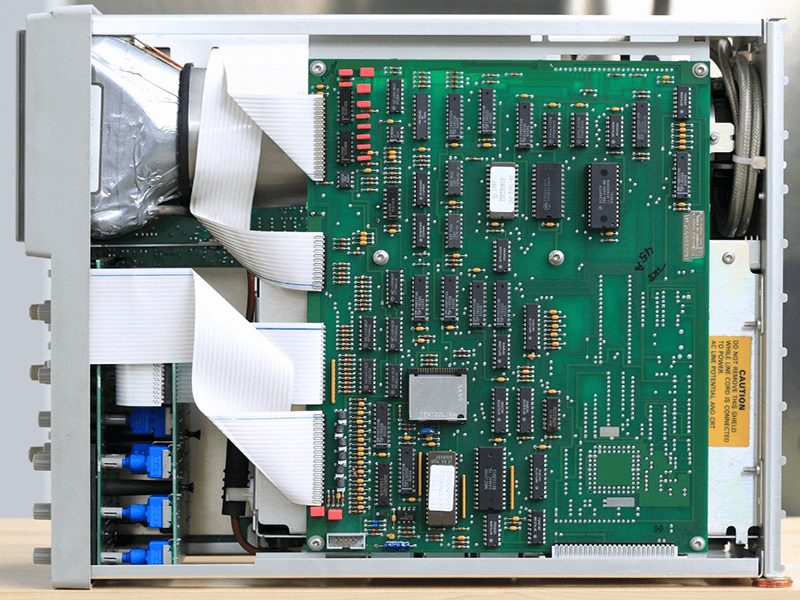
Routing determines whether the harness survives the life of the product. Wires should be kept away from sharp edges, heat sources and moving parts, kept clear of components that run hot, and supported at intervals so that the weight is not carried by the termination. Where a wire crosses a metal edge, it should be protected with a grommet or a sleeve, because vibration will eventually wear through the insulation even if the edge is not visibly sharp.
Bundling holds the routing in place and keeps the assembly tidy, but it must not crush the wires. A tie that is tightened onto a bundle deforms the insulation and can damage the conductor underneath, particularly on a small wire. The correct tension is one that holds the bundle without indenting it, and the position of the ties should be defined so that the routing is repeatable between units. Build records help when a routing defect appears on some units but not others.
Strain Relief and Service Loops
Strain relief transfers the pull from the conductor to the structure. Where a cable enters an enclosure, the relief may be a gland, a clamp, a tie to a fixed point or a moulded feature, and the requirement is that the conductor terminations see no load. A cable with no relief will eventually pull on the connector, and the failure appears as a broken wire at the crimp rather than at the point where the force was applied.
A service loop is left deliberately so that a connector can be unmated and the assembly moved without stressing the wiring. The loop should be planned rather than improvised, because too long a loop creates a tangle that can be pinched when the enclosure is closed, and too short a loop means the wiring is stretched during service. Both are common, and both are visible in the design rather than in the assembly.
Labelling and Identification
Wires and cables should be identified at both ends, with a label that survives the environment and the handling. The label should match the schematic, and where the same connector type appears more than once, the identification is what prevents a swap. In a dense enclosure, a missing label turns a five-minute service task into an hour of tracing.
The labelling scheme should be defined in the design and printed rather than written by hand. Hand-written sleeves are difficult to read, smudge and are applied inconsistently, and they also make it impossible for a second person to verify the identification. Where the harness is supplied by a subcontractor, the same scheme should be specified in the purchase documentation. Visual inspection should include a check of the labels at both ends.
Routing Inspection and Continuity
Inspection of the wiring covers the routing path, the bundling, the relief, the labels and the terminations. The routing path is checked against the drawing, which for a complex enclosure may need a photograph or a three-dimensional model rather than a two-dimensional view. Where the check is subjective, a reference photograph of the correct routing removes the ambiguity.
Electrical verification covers continuity, isolation and, where the connection must be robust, a pull test on a sample of crimps. Continuity alone will not detect a crimp that is marginal, because the connection may be mechanically intact at the moment of test. A pull test or a crimp height measurement is the check that addresses the mechanism rather than the symptom, and it should be applied at a defined frequency. Electrical test practice applies to the same connections.
Handling and Damage Prevention
Wiring is damaged by handling before it is damaged in service: a harness dragged across a bench, a connector dropped on the floor, a cable used to lift the assembly. The handling method should be defined for the specific product, and where the harness is heavy or awkward, a support or a fixture should be used. This is the same principle that applies to boards, and it is often neglected because wiring looks robust.
Incoming harnesses should be inspected on receipt, because a supplier’s crimp defect will otherwise be discovered at the customer. The checks are the crimp condition, the terminal type, the wire gauge, the labels and the length, and a sample is usually sufficient once the supplier’s process is established. Document control keeps the specification that the inspection is measured against.
Working with a Harness Supplier
Where the harness is built by a subcontractor, the drawing has to be complete enough for them to build it without asking questions: wire type and colour, length with tolerance, terminal part numbers, crimp specification, label content and the routing of a branch. A drawing that shows the topology but not the details produces a harness that is electrically correct and mechanically different from the one that was tested.
The supplier’s process should be qualified in the same way as any other, with a first article that includes a pull test and a dimensional check. Where the harness is a critical item, periodic re-verification keeps the process honest, and the results should be recorded against the part number rather than against the shipment.
FAQ
Why does a crimp pass continuity and fail later? Because the deformation is insufficient. A pull test or a crimp height check detects the condition that continuity cannot see.
How tight should a cable tie be? Tight enough to hold the bundle, loose enough not to indent the insulation. Crushing the insulation damages the conductor underneath.
What is a service loop for? To allow the connector to be unmated and the assembly moved without stressing the wiring. Its length should be planned, not improvised.
Should both ends of a wire be labelled? Yes. Identification at both ends is what allows the connection to be verified and the wiring to be serviced.