
Shear and Pull Testing of Solder Joints
A solder joint can be pulled, sheared or bent, and each test measures a different property. The result is a number that describes the joint and the process that made it, and it is only comparable with another number taken the same way.
What Each Test Measures
A pull test applies a tensile load along the axis of a lead or a wire, and it measures the strength of the joint and of the lead together. A shear test applies a lateral load at a defined height, and it measures the joint without loading the lead.
The choice follows the joint. A through hole lead is pulled and a surface mount chip is sheared. Our joint criteria notes define the acceptance that the figures support.
The test speed and the tool height are part of the specification, because the result changes with both. A faster shear speed reports a higher force, and a tool that sits closer to the board loads the joint differently from one that is higher.
The figures are therefore quoted with the conditions rather than alone. A number without its speed and its height cannot be compared with another. Our board quality notes describe how the sample is selected.

The force is one result and the failure location is the other. A joint that fails in the bulk alloy is a joint whose alloy is the weak item, and one that fails at the pad means the pad adhesion or the interface is the weak item.
The location is read from the tested part and it is often the more useful of the two results. A force that is inside specification with a failure at the pad is a warning that a force alone does not show.
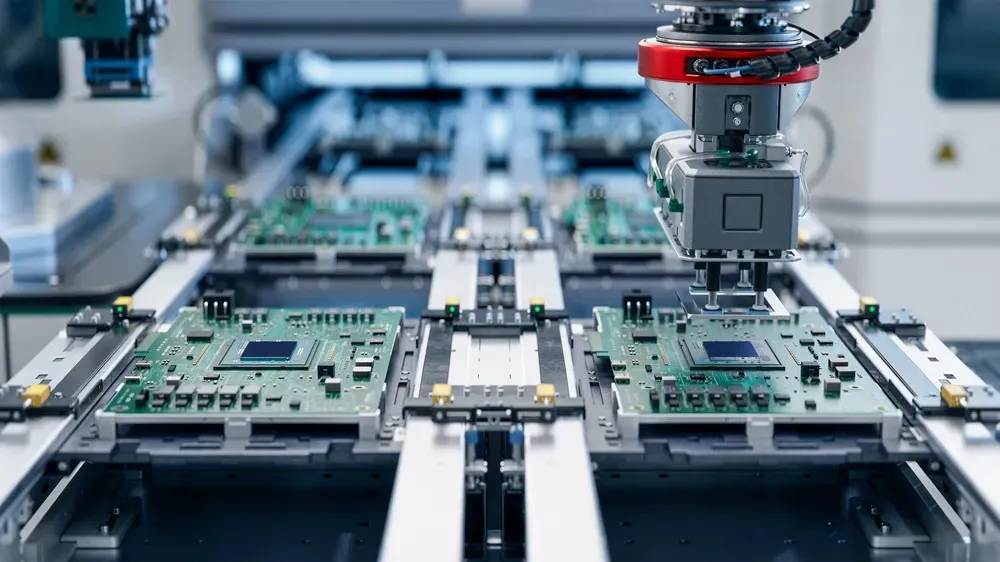
The test destroys the joint, so it is applied to a sample. The sample is taken from the production panel and it has the same copper and the same process as the product.
A sample that is built separately measures the sample. The sample is taken at the same positions on the panel as the product so that the plating distribution is represented. Our thermal cycling notes describe the related test that establishes the life.
A change that affects the joint is verified by the test rather than by the appearance. A change to the paste, the profile or the finish is a change to the joint and it is re-tested.
The re-test uses the same conditions so that the two figures are comparable. A re-test at a different speed answers a different question.
The record is the test method, the speed, the height, the force, the failure location and the sample position. With those, a change in the result can be attributed.
The trend across batches is more useful than a single figure, because it shows the direction of the process. A batch inside specification is a batch that passed and not a batch that is stable. Our first pass yield notes describe how the trend is used.
Acceptance and Its Evidence
Where the process window is narrow, the measurement resolution has to be better than the window, or the data cannot distinguish a good part from a marginal one. Where two operations share a tolerance, the allocation between them should be explicit rather than left to whichever is measured first.
The narrowest feature on the board usually sets the process window for the whole product, so it deserves the closest attention at review. Where a requirement can be measured, it should be measured at the point of manufacture and recorded against the board or the lot it applies to.
Sampling is a compromise between cost and confidence, and the sample size should follow from the failure rate that has to be detected. Where a decision is made by judgement, a boundary sample makes the judgement repeatable between operators and between shifts.
Where a process is at the edge of its capability, the margin should be bought deliberately rather than discovered during production. A record that identifies the operator, the date and the settings is worth more than a record that identifies only the result.
A measurement taken at the wrong point of the process describes the wrong thing, however carefully it is made. Where the supplier and the user both measure the same property, they should agree on the method before the first delivery.
Checks Before Release
Where an operation cannot be verified afterwards, it has to be controlled during the operation, and that control has to be visible in the record. Documentation exists so that a person who was not present can reproduce the work and reach the same conclusion.
Handling between operations is part of the process, and the damage it causes is often attributed to the operation that preceded it. A parameter that is set once and never re verified drifts, and the drift is usually discovered by a defect rather than by the record.
The cost of verification is small compared with the cost of a field failure, and it is paid at a point where the product can still be corrected.
Verification and Records
The acceptance criteria should be written before the work starts, so that the decision is made by the specification rather than by the person inspecting.
Is a higher force always better? It indicates a stronger joint and it says nothing about whether the joint will survive thermal cycling.
Can the test be done on the product? It can on a sample of the production, and the tested joint is destroyed.
What does gopcb provide for joint testing? We provide the method chosen for the joint type, speed and tool height specified with the force, the failure location recorded as well as the force, samples taken from product panels at defined positions, the same conditions used after a change, and a trend across batches.
Points to Confirm at First Article
The checks that matter are the ones performed on the product rather than on a sample kept for the purpose, because a coupon that travels with the panel is the only evidence about that panel. The tooling, the material and the profile form one system, and a change to any of them should be assessed against the other two before it is released.
The first article confirms that the setup matches the intent, and it is the cheapest point at which a wrong setup can still be corrected.