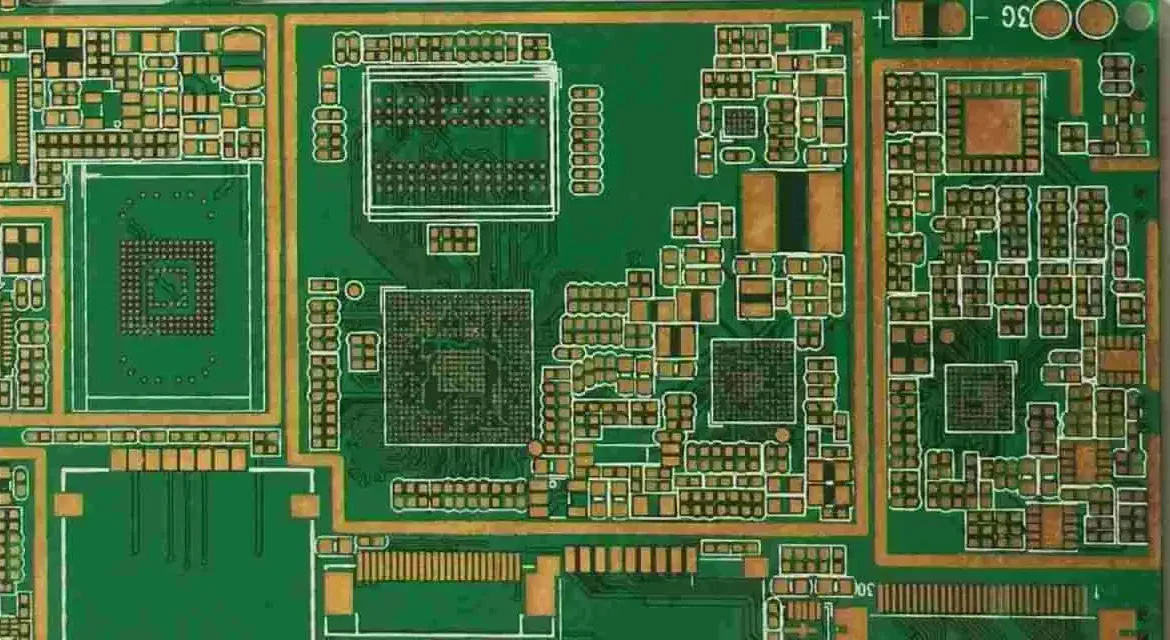
Solder Beading in Reflow: Print, Paste and Profile Causes
Solder beading is one of the few defects that is created before the board reaches the oven and only becomes visible after it leaves. The paste that forms a bead was printed in the wrong place, and every process between the print and the reflow decides whether that surplus stays harmless or becomes a cluster of spheres bonded beside a pad. This article follows the defect from the stencil aperture to the reflow profile and gives the order in which the causes should be corrected.
What Solder Beading Actually Is
Solder beading is a cluster of small spheres, typically 0.05 to 0.2 mm in diameter, sitting beside a joint and bonded either to the pad or to the mask rather than to the component. It is distinguished from random solder balling by its position: beads appear at the edge of a pad or in a line, and they survive cleaning because they have reflowed and alloyed.
The mechanism is a volume of paste printed outside the pad area, pushed there by stencil release or by slump, and then reflowed before the main joint can wet back to the pad. The paste is connected to the joint only through the mask opening, and once the alloy melts that connection breaks and the surplus stays where it was printed.
Stencil Aperture and Paste Release
The area ratio of the aperture governs how much paste leaves the stencil with the pad. Below an area ratio of about 0.66 the paste tends to stay in the aperture and is then smeared onto the mask by the following print stroke, and that smear is the raw material for a bead. The dimensional rules behind this are in our paste volume guide.
Aperture shape matters as well. Rounded corners and a slight inward taper on the wall release more cleanly than a sharp rectangle, and paste that does not release cleanly is exactly the paste that ends up beside the pad. The separation speed of the stencil from the board is part of the same setting and should be slow enough to let the paste shear rather than tear.
Release is checked on a test print rather than on production. A board with apertures blocked and paste deposits weighed before and after the print quantifies how much material is being left behind.
Stencil Wipe and Underside Contamination
The underside of the stencil collects paste with every print, and a wipe that is too infrequent, or a vacuum wipe that has stopped working, transfers that paste onto the mask of the next board. The deposit is thin, it lies outside the aperture pattern, and it looks like nothing until the assembly is reflowed.
Wipe frequency belongs in the print recipe and is set from a measured deposit rather than from habit. A useful check is to print onto a masked coupon with no apertures open and weigh it before and after, so that the transferred mass is a number rather than an impression.
Paste Rheology, Slump and Storage
Paste that has warmed up too quickly, or that has stood on the stencil, loses viscosity, and paste slump widens the deposit beyond the pad, and paste outside the pad is separated from the joint when the alloy melts. The effect is worse on a warm, humid floor than in a conditioned print room. Our warm up and shelf life notes give the timing.
The warm-up sequence and the time a jar is allowed to sit on the machine both belong in the process document. Paste that has been out beyond the manufacturer working time should be discarded rather than stirred back into the supply, because the rheology that was lost cannot be recovered by mixing.
Reflow Profile and the Vaporisation Path
A fast ramp lets flux volatiles escape quickly, and the escaping gas can eject small volumes of paste from the pad before the alloy coalesces. A slower preheat, and a soak long enough to bring the whole assembly to within 20 degrees of the flux activation range, reduces that ejection. Zone settings for that shape are discussed in our zone settings guide.
The other profile variable is time above liquidus. A short time leaves beads that have not fully coalesced, while an excessive one oxidises the paste and raises the surface tension that holds the beads in place. The window is narrow on fine pitch work and has to be verified on the product rather than on a test coupon.
Pad, Mask and Via Geometry
A solder mask dam narrower than the print tolerance lets paste bridge two pads and split into beads when the alloy melts. Keeping the dam at least 0.1 mm wide, and asking the fabricator to hold mask registration within 0.05 mm, removes most geometry-related beading.
Vias beside a pad can absorb or release material during reflow, and a via that is tented but not plugged can vent onto the mask and carry paste with it. Where beads appear in a line beside a row of pads, the first thing to measure is the via structure rather than the stencil.
Placement Force and Component Stand-off
The placement force presses the component into the paste, and the displaced paste has to go somewhere. On a small chip component the surplus flows along the termination and off the pad, where it becomes a bead after reflow. Reducing the placement force and the nozzle over-travel removes that displacement.
Stand-off matters for the same reason. A part pressed until it touches the mask leaves no room for paste beneath it, and everything squeezed out lies outside the wetting area. The stand-off is set by the placement height in the machine programme, not by the pad design, so it can be corrected without a new stencil.
Detection and Quantification
Beads are visible after reflow and invisible before it, so most programmes catch them at inspection when they are already a defect. The minimum detectable sphere should be set close to the smallest bead the customer rejects, and that limit should be stated in the inspection specification rather than left to the algorithm default. Cameras and lighting for this are covered in our AOI guide.
Counting beads per board and recording their position gives the diagnosis. Beads along one stencil edge point to a print problem, beads beside a single component point to placement, and beads spread across the board point to paste condition or profile. The counts belong in the process record beside the print parameters.
Corrective Action Order
The cheapest correction is the print: check the wipe, the stencil underside, the paste condition and the separation speed before changing anything else. Only when the print is demonstrably clean does it make sense to examine the profile, and only after that the pad and mask geometry.
Each change is verified with a counted bead rate rather than with a visual impression, recorded before and after so that the effect is attributable. A process brought inside the limit by three simultaneous changes cannot be optimised afterwards, because nobody knows which change mattered.
Beads are easiest to eliminate when the print is characterised first. A test print with a known aperture set, weighed before and after separation, shows how much paste is being left on the mask before any production board reaches the oven.

A bead count taken on thirty consecutive boards at the same position is the number to track, because a shift in that count after a stencil or paste change is the evidence that the change actually did something.
FAQ
Do solder beads mean the paste is bad? Not necessarily. Paste condition is one of several inputs, and beads appearing in a line beside one stencil edge are usually a print or wipe problem rather than a material problem.
Can beads be cleaned off after reflow? Cleaning does not remove them, because a bead that has reflowed is metallurgically bonded to the mask or the pad. It is removed mechanically or by rework, and the assembly is then re-inspected for the short circuit risk it represented.
What area ratio should the stencil hold? Keep at least 0.66 for reliable release. Below that, paste stays in the aperture and is transferred to the mask by the next print stroke.