Electrical Test Coverage: Continuity and Isolation Design
Electrical test is measured in coverage, and coverage is a property of the design rather than of the tester. A board with inaccessible nets cannot be tested however good the equipment is, and a board whose coverage is not documented cannot be shown to have been tested at all. This article covers what continuity and isolation testing can find, how coverage is defined and the layout decisions that keep it high.
What Electrical Test Detects
Continuity testing confirms that a net is connected end to end, and isolation testing confirms that it is not connected to any other net. Together they detect opens, shorts, wrong values in some cases and a class of assembly errors that no optical inspection finds.
What the test does not detect is a connection that is present but marginal, such as a plated barrel with a thin wall or a solder joint with reduced area. Those conditions pass a continuity measurement and fail later, which is why the test is a screen rather than a proof of quality.
How Coverage Is Defined
Coverage is the proportion of nets, or of testable nodes, that the programme measures, and it is quoted against a defined denominator. Quoting coverage against nets and against nodes gives two different numbers for the same board, so the definition belongs in the specification.
A net that has one accessible node can be tested for isolation but not for continuity, because continuity needs two points. That distinction is what makes node coverage the more informative figure on a dense board.
Access and Layout
Test access comes from test points, from pads and vias that can be probed, and from connectors in some cases. A net with no accessible point cannot be measured, so the layout is where coverage is won or lost.
The layout rules that matter are a minimum test point size, a keep-out around tall components, spacing between adjacent points and a ban on probing surfaces that would be damaged. Applied as design rules, they produce a board that can be tested; applied as a review comment at the end, they produce a board that is nearly testable.

Coverage is predicted by the design rule checker before the board is fabricated, which is the only point at which an inaccessible net can be corrected cheaply.
Untestable Nets and How to Handle Them
Some nets are untestable in practice: a shielded net, a net buried between planes, or one whose only node is under a connector. The answer is to document them and to cover them by another means, such as functional test or a destructive sample check.
Documenting them is the part that is usually skipped, and the consequence is that a later change removes the last measurement without anyone noticing. The list of untested nets belongs with the test programme rather than in a design review note.
Test Method and Its Limits
A bed of nails fixture measures all the points simultaneously, which is fast and which requires the access on one side. A flying probe measures sequentially and can reach both sides, which is slower but requires less tooling.
The choice follows from volume, from the number of nets and from whether the access exists. A board designed for flying probe access can usually be tested on a fixture as well, while the reverse is not true.
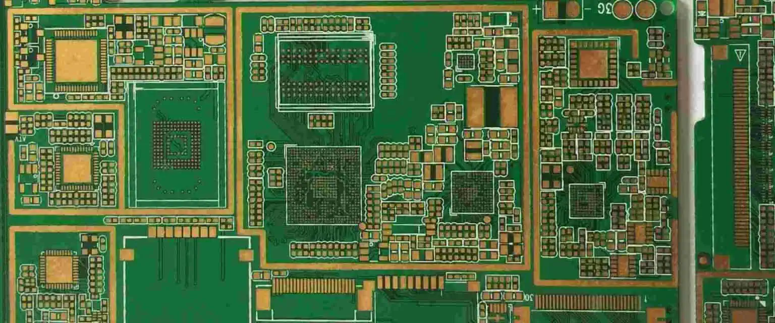
The access requirement of the two methods differs, so the layout is designed for the method that will be used in production rather than for the one available in the laboratory.
Programme Development and Verification
A test programme is verified by introducing known faults on a sample board, opening one net and shorting two others, and confirming that the programme reports both. A programme that has never been challenged in this way may be measuring the wrong nodes.
The programme also has to be maintained when the layout changes, and the maintenance is recorded so that the coverage figure can be recalculated. A revision that adds a net without a test point reduces coverage, and the reduction should be visible rather than discovered later.
False Failures and Their Cost
A false failure costs more than a missed defect in the short term, because it stops production and consumes engineering time. The common causes are a probe that has worn, a test point that has been covered by mask, and a threshold that is too tight for the resistance of a long thin trace.
Where false failures repeat at one position, the cause is usually mechanical rather than electrical, and the position is examined before the programme is adjusted. Adjusting the threshold to remove a false failure can also remove the ability to detect a real one.
Interaction with Assembly and Rework
Test points are probed after soldering, so they carry witness marks into the finished product. Where a mark is unacceptable, the test point is placed on a pad that is not part of the final appearance or the board is tested before the final process step.
Rework after test invalidates the test result for the affected area, which is why rework is followed by a re-test of the nets concerned rather than by an inspection only. The rule belongs in the process documentation rather than being left to the operator’s judgement.
Documentation and Reporting
The test specification should name the method, the coverage definition, the access requirement and the treatment of untestable nets, together with the acceptance criteria for a witness mark. Those items make the test reproducible between suppliers and between sites.
The report that accompanies a batch should carry the programme revision, the coverage figure and the list of untested nets, so that the customer can see what was and was not measured. That report is the evidence that the test was performed as specified. The acceptance of the board as a whole is described in our board quality guide.
Points to Confirm at First Article
Handling between operations is part of the process, and the damage it causes is often attributed to the operation that preceded it. A change that is not recorded is a change that cannot be explained when the result moves, which is why the record is part of the process.
The checks that matter are the ones performed on the product rather than on a sample kept for the purpose, because a coupon that travels with the panel is the only evidence about that panel.
Related reading: our fabrication notes, board quality and design release notes cover the same ground.
Documented Process Control
A parameter that is set once and never re verified drifts, and the drift is usually discovered by a defect rather than by the record. The first article confirms that the setup matches the intent, and it is the cheapest point at which a wrong setup can still be corrected.
FAQ
What coverage figure should be required? It depends on the product, but the figure should be defined against nodes rather than nets, and the untested nets should be listed by name.
Can a bed of nails test be converted to flying probe? The access usually allows it, because flying probe needs less than a fixture, but the programme has to be rewritten and verified with known faults.
Why do false failures cluster at one position? Usually a mechanical cause, such as a worn probe or a test point covered by mask, rather than a threshold that is set too tightly.