Tape and Reel Packaging Requirements for SMT Feeders
Packaging is the part of a component delivery that the line interacts with as a mechanism rather than as a product, and a tape that is slightly out of specification stops a feeder rather than failing an inspection. The requirements are published in standards, and they are worth reading as a set because pocket size, cover tape peel force and pitch act together. This article covers the parameters, how they are measured and how a packaging fault presents itself on the line.
What the Carrier Tape Has to Do
The carrier tape holds each component in a pocket at a defined pitch so that the feeder can index it to the pickup position. It has to protect the part during transport, allow the cover tape to peel without lifting the component and present the part at a height the nozzle can reach.
Those requirements conflict: a deeper pocket protects the part but makes pickup harder, and a shallower one presents it well but allows it to move. The pocket depth is therefore specified as a range rather than a minimum, and the range is tied to the component thickness.
Pocket Size and Component Fit
The pocket is sized so that the component sits within it without rotating, typically allowing 0.1 to 0.2 mm of clearance on each side for a small chip part. A pocket that is too large lets the part turn during indexing and the feeder presents it at an angle.
Pocket depth is set so that the top of the component sits just below the tape surface, which keeps the cover tape from pressing on the part while still allowing the nozzle to reach it. For a very thin part, a shallower pocket is used with a support web beneath it rather than a deeper cavity.
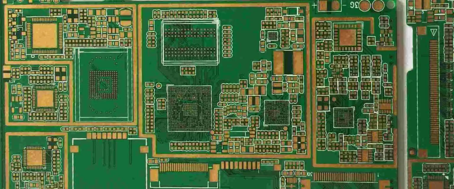
Pocket dimensions are verified with a gauge or optically at goods inwards on a sample, because a tape that is out of specification fails on the feeder rather than at inspection.
Cover Tape Peel Force
Cover tape is specified by peel force, with a typical range of 0.1 to 0.7 newtons measured at a defined angle and speed. Below the range the tape can lift during handling and spill components, and above it the feeder stalls or the tape tears.
The peel force depends on the seal width and on the sealing temperature used by the component packager, so two deliveries of the same part can differ while both claim the same tape. The measurement is made on the production feeder where a dispute arises, because the peel angle on the machine is part of the result.
Pitch, Sprocket Holes and Indexing
The sprocket holes position the tape on the feeder, and their pitch and their position relative to the pockets define where each component stops. A cumulative pitch error across a reel moves the pickup position gradually, which the machine compensates for until it cannot.
Sprocket hole quality matters as well, because a hole that is partly punched or has a burr causes the feeder to index incorrectly by one position. The result is a run of misplaced components rather than a single error, and the pattern is recognised by where it starts.
Reel Format and Handling
The reel diameter, the hub, the tape wind direction and the leader length are all specified, and a mismatch between the reel and the feeder is a mechanical problem rather than a component problem. Leader and trailer lengths have to be long enough for threading and for the last component to reach the pickup point.
Reels are stored upright, in their packaging, and they are handled by the hub rather than by the tape. A reel that has been dropped distorts the tape at the point of impact, and the damage appears later as a single stuck pocket somewhere in the middle of the reel.
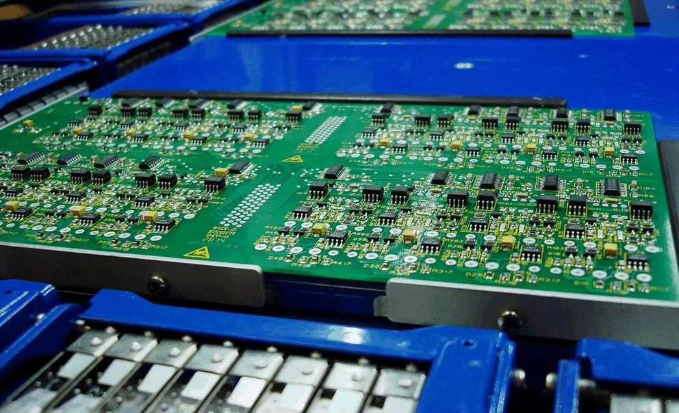
The wind direction is worth checking on receipt, because a reel wound the wrong way cannot be threaded without unwinding it, which risks damage to the components.
How Packaging Faults Appear on the Line
Most packaging faults present as feeder faults: repeated pick failures at one position, components presented at an angle, or a tape that stalls and has to be re-threaded. The feeder records the failed picks, which localises the problem to a position rather than to the product.
Where the failures are periodic rather than random, the pitch or the sprocket holes are the likely cause. Where they are random, the pocket size or the presence of debris in the tape is more likely, and the reel is inspected rather than the machine adjusted.
Incoming Verification of Tapes
Incoming verification measures the pocket dimensions, the peel force on a sample, the pitch over a length of tape and the reel format. The measurements are quick and they are taken before the reel reaches the line, which is the only point at which the material can be returned without disrupting production.
The sample is taken from the beginning, the middle and the end of the reel, because a sealing temperature that drifts during packing produces a peel force that changes along the length. A single sample from the leader would miss that entirely.
Moisture Sensitive Parts and Packaging
Components with a moisture sensitivity level are packed in a moisture barrier bag with desiccant, and the tape itself may be affected by the bake that follows. A bake at the temperature recommended for the component can soften or distort some carrier tapes, which then fail on the feeder.
Where baking is required, the tape is checked afterwards on a sample rather than assumed to have survived, and the bake temperature is matched to both the component and the tape. The handling of those parts is described in our fabrication notes.
Specification and Records
The purchase specification should state the tape width, the pocket dimensions, the pitch, the peel force range and the reel format, and it should require a sample measurement with the delivery. Without that, a delivery is accepted on the strength of a data sheet that describes the tape the packager intended to use.
The records worth keeping are the incoming measurements, the feeder fault history and the lot numbers of any reel that caused repeated stoppages. Together they give a supplier quality figure that is based on line behaviour rather than on a certificate. The line behaviour itself is reflected in the first pass yield record.
Points to Confirm at First Article
The first article confirms that the setup matches the intent, and it is the cheapest point at which a wrong setup can still be corrected. The cost of verification is small compared with the cost of a field failure, and it is paid at a point where the product can still be corrected.
Related reading: our fabrication notes, board quality and design release notes cover the same ground.
Additional Considerations for This Build
Practical attention to tape and reel pays for itself here, because it decides whether the finished board behaves as the drawing intended. Where the requirement is not stated on the fabrication drawing or in the assembly notes, the shop has to assume a default, and that default is rarely the value the design was simulated with. Stating tape and reel explicitly, together with the tolerance that applies, removes the assumption and keeps the result predictable from batch to batch.
FAQ
What peel force should be specified? Between 0.1 and 0.7 newtons at the standard angle and speed, with the actual value confirmed on the production feeder.
Why does a component arrive rotated? Usually a pocket that is larger than the component, which lets it turn during indexing before the nozzle reaches it.
Can a reel be re-used after baking? Only after the tape has been checked, because some carrier tapes distort at the temperatures used to dry moisture sensitive parts.