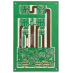
Copper Foil Roughness: Skin Effect, Insertion Loss and HVLP Options
At low frequencies the surface of a copper trace is a detail, but as the skin depth shrinks towards the profile of the foil, the current is forced to follow every peak and valley. The path becomes longer than the trace, the loss rises and the effect is invisible in the design tools unless the foil is specified.
What Roughness Means at the Foil Interface
Copper foil roughness is quoted as an Ra or an Rz value measured on the treatment side of the foil, which is the side bonded to the laminate. A standard electrodeposited foil has a profile in the region of 1 to 3 micrometres, a very low profile foil sits near 1 micrometre and an HVLP foil is below about 0.5 micrometres.
The foil is treated to bond to the resin, and the treatment is what creates the profile at the scale that matters at high frequency. The measured value therefore belongs to a specific foil and a specific treatment, and quoting a number without the product name is not a specification.
Skin Effect and Why Roughness Costs Loss
Current in a conductor concentrates near the surface, and the depth of that concentration falls as the square root of frequency. At 10 GHz the skin depth in copper is under one micrometre, which is smaller than the profile of an ordinary foil, so the current has to follow the contour rather than a straight path.
Following the contour lengthens the current path and raises the resistance, and it also increases the phase delay in a way that is not captured by a simple resistance term. The result is a measured insertion loss that is higher than the value calculated from a smooth conductor, and the gap grows with frequency. The effect is also asymmetric, because the reference plane under a trace is often rougher than the trace itself and its contribution never appears in the signal layer artwork.
Measuring Roughness
Roughness is measured with a stylus profilometer or an atomic force microscope on a foil sample, and with optical or laser methods on a laminated cross section where the foil is bonded. The two measurements do not agree exactly, because lamination presses the profile into the resin and changes it.
For design work the supplier’s foil data is used, with the caveat that the value is quoted for the treatment as supplied. For qualification, the foil is measured after lamination as well, because the pressed profile is the one the current sees, and our copper thickness measurement notes describe the cross section preparation used for that check.
Foil Types Available
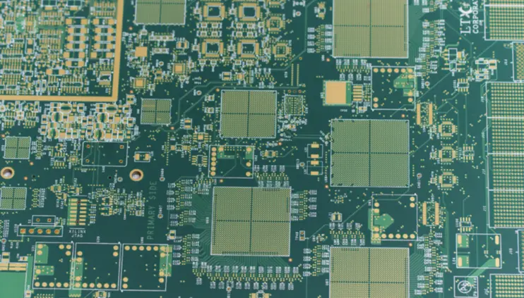
Standard electrodeposited foil is the cheapest and the roughest, and it suits digital boards where the loss budget is not tight. Reverse treated foil has a smooth matte side for the conductor and a rough treated side for bonding, which separates the electrical surface from the mechanical one.
Very low profile and HVLP foils push the profile down further, to below about 0.5 micrometres in the best grades, and they are used on high speed digital and on radio frequency boards where the loss budget is measured rather than estimated. The premium price is real, so the choice is made from the data rate and the trace length together. The gauge of the foil moves with the treatment as well, because a flatter profile is rolled differently, and that difference shifts the impedance unless the stackup is adjusted with it.
The Adhesion Trade-off
A smooth foil bonds less well, because the mechanical keying between the treatment and the resin is reduced. Peel strength figures of about 1 newton per millimetre are expected of a standard foil, and a low profile product has to reach the same figure through chemistry rather than through roughness.
That chemistry is in the treatment, and it also shows up in the process window of the laminate rather than the foil alone. Where a low profile foil is being introduced, the peel test after lamination is part of the qualification, because a bond that is marginal will separate during drilling or at reflow temperature. Peel strength is measured on a coupon built with the same laminate and the same lamination cycle, and the result is compared against the supplier’s minimum figure rather than against an internal average.
Building the Loss Budget
Insertion loss is the sum of conductor loss, dielectric loss and the reflections from the structure, and the roughness contribution sits entirely in the conductor term. Above about 10 GHz the dielectric term grows quickly as well, so changing the foil alone may not fix a budget that is dominated by the resin.
The way to see the split is to measure two coupons that differ only in the foil, on the same laminate and the same stack, and compare the loss curves. That comparison turns the roughness contribution from a modelled number into a measured one.
Impedance, Line Width and Etching
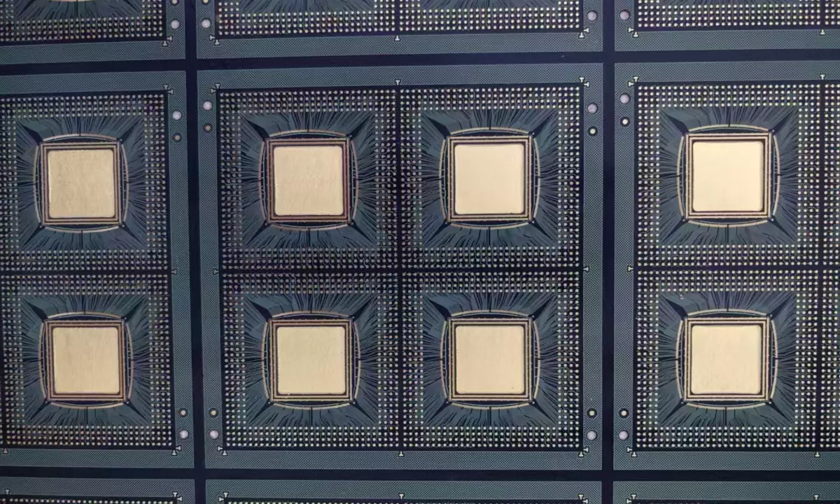
A smooth foil etches differently from a rough one, because the profile acts as an anchor for the resist and for the etchant. The same artwork on a low profile foil can produce a slightly narrower trace, and on a controlled impedance line that shifts the impedance in the direction nobody expects.
The etch factor is therefore checked after a foil change, and the line width is measured on a production coupon rather than assumed to be unchanged. Where the design is at the edge of its impedance tolerance, the measurement is repeated on the first panel of the new foil, as set out in our production process flow notes.
Selecting the Foil for a Stack
The selection starts from the data rate, the longest trace on the board and the loss budget for that trace. A 25 Gbps link with a 300 mm channel has a different answer from a 10 Gbps link with a 50 mm channel, and the second may not justify an HVLP foil at all.
The availability of the foil in the required thickness and the supplier’s minimum order also enter the decision, because a foil that cannot be supplied in the build time is not a choice. Where the volume is small, a reverse treated foil on a low loss laminate is a common compromise.
Verification and Documentation
The verification is a coupon with the same stack and the same foil, measured for insertion loss over the frequency range that matters, and a cross section that shows the copper profile at the interface. The coupon is kept so that a later batch can be compared against it, and its frequency range should extend to the Nyquist frequency of the link rather than stopping at the clock, because the eye height depends on the harmonics.
The drawing should name the foil by product and by its roughness figure rather than by a general description, since two products can be called low profile and differ by a factor of two. Our fabrication notes set out how the foil and the laminate are named together so that the stackup is unambiguous.
FAQ
Does a smooth foil always reduce loss? It reduces the conductor part of the loss, which is the part that grows with frequency in a rough foil. A board whose loss is dominated by the dielectric will show only a small improvement, which is why the two coupons are measured side by side.
Can roughness be measured on the finished board? It can be measured on a cross section, but the value differs from the supplier’s data because lamination presses the profile into the resin. The cross section is used to confirm the foil type rather than to derive a design number.
Why does the foil affect trace width control? Because the treatment anchors the resist and guides the etchant, so the same artwork produces a slightly different width. The difference is small in absolute terms and significant on an impedance controlled line, which is why the coupon is measured after a change.