SMT Changeover First Article: Setup Verification Before Volume
A changeover replaces almost every variable in the process at once, and the first article is the only point at which a wrong setup can still be corrected without scrapping product. Treating it as a formality is what turns a routine changeover into a shift of rework.
What a Changeover Actually Changes
A changeover changes the feeders, the placement programs, the stencil, the paste lot, the support tooling and often the reflow recipe. Each of those is a potential source of error, and the errors compound: a placement offset of 0.05 mm that would be harmless on a 0603 chip is a bridge on a 0.4 mm pitch QFN. The purpose of a first article is to verify the combination, not to verify each item in isolation.
The changes that catch teams out are the quiet ones. A feeder that was left in the cart from the previous product, a nozzle changed during the last shift without a record, a support block that was not returned to its position, a paste lot that was opened yesterday and has been on the machine since. None of these show up in a checklist that only asks whether the program was loaded. For that reason the first article should be built on the same machine, with the same paste and the same stencil that production will use, and it should be run after the line has reached its working temperature rather than on a cold machine. A first article taken ten minutes after start up often passes and the boards that follow do not, because the paste and the machine have not yet stabilised.
Feeder Setup Verification Before the First Board
Feeder verification starts with identification. Confirm that every position holds the part number called for in the program, that the reel label matches the loading list, and that the parts are not substitutes. Then verify the mechanical state: tape peeling force within the feeder’s specification, pickup height set from the component thickness rather than from the previous product, and the feeder locked down so that vibration cannot move it.
The feeding performance itself is worth measuring once per changeover. Run each feeder through a sample of picks and record the pickup rate; a feeder that misses one part in a hundred will produce enough defects over a production run to matter. Feeders that fail this check should be replaced rather than adjusted, because the adjustment that fixes one miss usually creates a double pick a few hundred cycles later. Note also the parts that are hand placed or placed from a tray. They are outside the feeder check and are the most common source of a wrong orientation on a first article, because tray positions are rarely verified against the program image.
Paste Deposit Check: SPI as the First Gate
The first article should be measured at the printing stage before any component is placed, using the solder paste inspection system rather than a visual check. Compare the measured paste volume, area and height against the stencil design, and look at the individual apertures that drive the tightest joints: the thermal pads, the fine pitch rows and any aperture that is smaller than the stencil thickness allows.
Set the acceptance band from the product rather than from a generic table. A 0.5 area ratio aperture needs a wider volume tolerance than a 0.8 aperture, and the smallest aperture on the board defines the band that applies to the run. Record the first article SPI result with the panel serial number so that it can be compared with the SPI data from the production run; a first article that sits at the centre of the band and a production run that sits at the edge is a process that is drifting, not a process that is stable. Print a second board immediately after the first and measure both. Variation between two consecutive prints taken minutes apart is the best early indication of a paste or squeegee problem, and it costs nothing to collect.
Placement Offset Measurement on the First Article
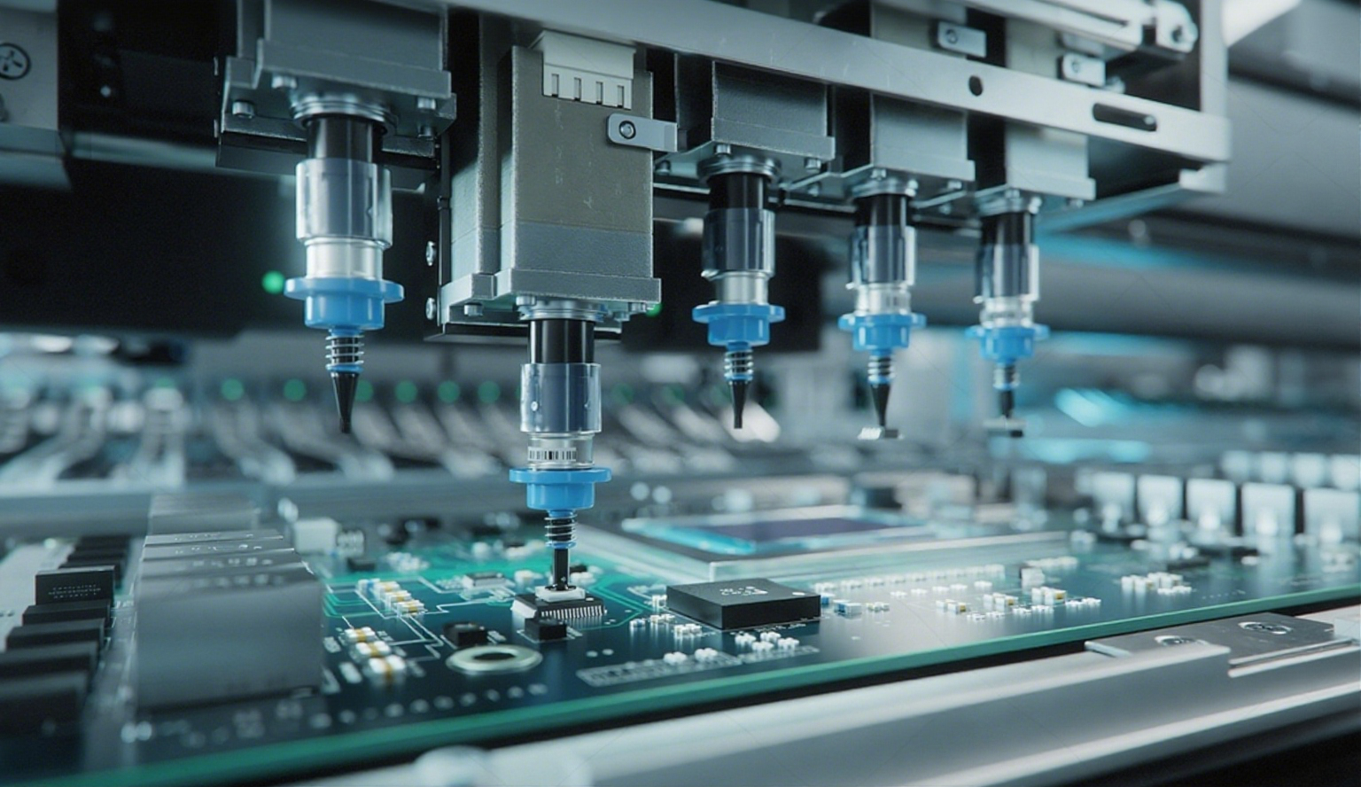
Placement offset should be measured, not judged by eye. Use the placement machine’s own vision or a separate optical system to compare the pad edge with the component edge at a sample of positions across the panel, and record the offset in both axes. An offset of a quarter of the pad width is acceptable for a 0603; the same offset on a 0402 or a fine pitch device is not.
Measure at the corners of the board as well as the centre. A machine that is accurate at the centre and offset at the corners has a scaling or a fiducial recognition problem, not a nozzle problem, and adjusting the program to fix the corners will move the centre. Where the first article is offset in a consistent direction across the whole panel, check the fiducials and the board datum before touching the placement offsets. Keep the measurement rather than the verdict. Two numbers per axis per position take a few minutes to record and make it possible to tell, three months later, whether a machine has drifted or whether a product was always at the edge of its tolerance.
Reflow Profile Confirmation After a Changeover
A reflow profile is attached to a product, but it is executed by an oven whose condition changes with load, with exhaust and with the ambient air. After a changeover, confirm the profile as described in our reflow profile verification notes, using a profiled board of the same thickness, copper weight and component density as the product, and compare the measured peak, the time above liquidus and the soak against the recipe. Do not reuse the profiler board from a different product class.
The most common changeover error is to run a new product on the previous product’s recipe because the board looks similar. Copper weight and component mass change the thermal response far more than board dimensions, and a recipe that produces a 240 C peak on a light board can produce 230 C on a heavy one. Where the changeover involves a different solder paste alloy, re profile as a matter of course, because the liquidus temperature has changed. Attach the thermocouples to the same locations used when the recipe was qualified, and record the attachment method. A thermocouple held on with polyimide tape reads differently from one staked with adhesive, and the difference is large enough to change the decision about whether the profile passed.
Handling Reels, Splices and Part Substitutions
Reels that carry over from a previous run should be verified rather than trusted. A reel that was returned to stores with a partial quantity and issued again may have been spliced, and a splice introduces a joint in the tape that some feeders handle badly. Check the splice, confirm the part number and the date code, and count the remaining parts if the reel is close to the quantity the run requires.
Substitutions are the highest risk item in the whole changeover. A substitute part with the same value but a different body size changes the placement nozzle, the pad contact area and sometimes the solder volume required. Any substitution should be recorded against the panel serial number, and the first article should be built with the substitute in place so that the placement and the reflow are verified with the part that will actually be used.
Fixture and Support Changes
Support tooling is specific to the board, and it is the item most often left over from the previous product. A support pin left in the wrong position can lift a thin board under a connector and produce open joints on the next product. Photograph the support layout at the end of every run and compare the photograph with the layout at the start of the next changeover.
The same applies to conveyor width, edge clearance and any tooling that holds the board during printing. Verify conveyor width against the panel dimensions with a gauge rather than by eye, because a conveyor set 0.5 mm too wide lets the board move during printing and produces a deposit offset that looks like a stencil problem. Check the board support under the print area for flatness, and confirm that the tooling pins locate the panel without forcing it.
Deciding How Many Boards to Check
One board is the minimum, and it is rarely enough. A practical rule is to check the first board in full, then run three boards and confirm only the characteristics that are most likely to drift: paste volume, placement offset on the finest pitch part, and the presence and orientation of the parts that are hand placed. If all three are stable, release to volume.
Where the product has a history of a specific defect, add that characteristic to the sequence. A product that has previously produced tombstoned 0402s should have the paste volume on those apertures measured on every board of the check sequence. The first article is not a fixed checklist, it is a targeted verification against the known risk of the product being set up.
Records, Approvals and Release to Volume
The first article record should contain the panel serial number, the machine and line, the operators, the paste lot and stencil identification, the SPI result, the placement offsets measured, the profile with its peak and time above liquidus, and the name of the person who approved the release. Without the approval, the check is an opinion rather than a gate.
Link the record to the production data rather than filing it separately. When the run subsequently produces a defect, the first article data shows whether the process started in control or started at the edge of its window, and that single fact decides whether the corrective action belongs to the setup or to the process. Compare the first article yield with the first pass yield of the run, and treat a large gap as a setup problem until it is proven otherwise.
FAQ
How many boards should be checked at a changeover? Check the first board in full, then run three more and verify the characteristics most likely to drift: paste volume, placement offset on the finest pitch device, and the orientation of hand placed parts. Add any characteristic that the product has previously failed on.
Does the reflow profile have to be re verified at every changeover? Yes, whenever the product changes. Confirm the profile with a board of the same thickness, copper weight and component density, and always re profile when the paste alloy changes, because the liquidus temperature has moved and the previous recipe no longer describes the same process.
What is the most common cause of a failed first article? A leftover from the previous product: a support pin in the wrong place, a feeder that was not removed, or a stencil from the previous run. Verify the physical setup as well as the program, and compare a photograph of the support layout taken at the start of the run with the documented layout.