Burn-in Test Rack Control: Wiring, Chamber Load and Failure Recording
A burn-in test is an accelerated life test, and its value depends entirely on whether the boards really experienced the stress that the procedure claims. Rack wiring, chamber loading and temperature verification decide that, and none of them can be inferred from the chamber set point.
What Burn-in Is Supposed to Prove
Burn-in exists to remove early life failures before the product reaches a customer. It does that by applying a combination of temperature and electrical load for a defined period, which accelerates the failure mechanisms that would otherwise appear in the first weeks of service. Because it is an acceleration, the stress has to be known and repeatable: a board that saw 85 C for 48 hours at full load has a different history from one that saw 70 C because it sat in a cold corner of the chamber.
That is why burn-in records are read as stress records rather than as pass or fail records. The number of board failures during the run is the headline figure, but the useful data are the load current, the board temperature and the duration each unit actually experienced. Where the sheet only records the chamber set point and the start and end times, the test cannot be interpreted and cannot be repeated. The distinction between screening and proving is also worth stating. Burn-in screens latent defects out of a population; it does not prove reliability. Reliability comes from the design and the process, and burn-in only shows whether a batch contains units that would have failed early.
Rack Wiring, Channel Mapping and Continuity
A burn-in test rack is a wiring harness with a set of loads and monitors for every position. The first requirement is that the wiring diagram and the physical rack agree, because a mis mapped channel is the most common cause of a board that passes burn-in while a fault goes unmonitored. Verify the mapping by applying a known fault to one position and confirming that the monitor reports it at the correct address.
Continuity and resistance checks belong at the start of every run, not only at rack build. Measure the supply resistance to each position and compare it against the value recorded when the rack was qualified; a rise of more than a small percentage indicates a worn contact, a corroded pin or a loose crimp. Log the measurement per position, because a fault that develops in one position is far easier to find when the trend is available. Keep the harness drawings with the board serial numbers that used each rack. When a field failure occurs, the ability to trace a unit back to a specific rack position and a specific run is the difference between a corrective action and a guess.
Contacting the Board: Sockets, Pogo Pins and Connectors
The board has to be connected reliably for tens of hours, and the contact method is where most burn-in problems originate. Spring loaded pins are convenient and wear quickly; a pogo pin rated at 100,000 cycles will have lost a significant part of its spring force after 30,000 insertions, and the resulting contact resistance will heat the tip and the pad. Sockets avoid the pad wear but introduce their own spring life limits and alignment requirements.
The practical approach is to specify a contact resistance limit for the burn-in interface and check it on a defined sample of positions before each run, using the same four wire technique applied to in circuit test fixtures. Where a board is connected by a mating connector rather than a socket, inspect the connector for mechanical damage and confirm the retention force, because a connector that works loose after a few thermal cycles will produce an intermittent that appears as a board failure. Mark the pads that carry the load current. They are the ones that will discolor first, and a discolored pad under a pogo pin means the contact resistance has risen enough to generate heat, which is a rack problem rather than a board problem.

Chamber Loading Density and Airflow
Chamber loading density changes the thermal environment more than the set point does. A chamber rated for 200 boards that is filled to capacity with closely spaced racks will have a board temperature well above the set point in the middle of the stack, because the dissipated power has nowhere to go. Chamber loading should be specified as a maximum, and the airflow around every board should be maintained rather than assumed.
Measure rather than estimate. Place thermocouples on boards at the bottom, middle and top of the rack and at the front and back of the chamber, and record the spread. A spread of more than 5 C between positions means the run is applying different stress to different units, and either the loading has to be reduced or the airflow has to be improved with fans or baffles. The same principle applies to the power dissipated. A rack full of boards drawing their maximum load generates far more heat than the same rack idling, and the chamber’s ability to hold temperature depends on the total wattage. Compute the total dissipation before the run and confirm it against the chamber’s rating at the set point, not at ambient.
Junction Temperature Versus Chamber Set Point
The chamber set point is the air temperature, and the junction temperature inside a component is what actually drives the failure mechanisms. The difference between them depends on the power dissipation, the thermal resistance from junction to ambient and the airflow over the board. A device dissipating half a watt with a thermal resistance of 60 C per watt sits 30 C above the surrounding air, so a chamber at 85 C creates a junction at 115 C.
That figure should be calculated for the hottest device on the board and confirmed by measurement where possible. Attach a thermocouple to the package surface or, better, use the device’s own temperature sensing diode if the silicon provides one. Where neither is available, measure the board temperature next to the device and add the calculated rise, and record the result with the run. Record the number against the device rating. A junction temperature that exceeds the maximum rating during burn-in will produce failures that are caused by the test rather than revealed by it, and those failures are indistinguishable from genuine defects unless the temperature has been measured.
Power Cycling and Load Profiles
Burn-in can be run at constant temperature and constant load, or with power cycling that switches the boards on and off at intervals. Power cycling adds a thermo mechanical stress that accelerates solder joint and via fatigue, and it is chosen when the product will see many on and off events in service. Constant load accelerates the mechanisms driven by temperature and voltage, such as oxide wear out and electromigration.
Choose the profile from the failure mechanisms that are relevant to the product, and state the cycle period and the duty cycle in the procedure. A cycle of ten minutes on and ten minutes off is not equivalent to five minutes on and five minutes off, even at the same average power, because the thermal excursion per cycle is different. Record the actual number of cycles delivered rather than the number intended. Where the load is applied through the board’s own firmware, verify the version loaded on each unit. A board that ran an earlier firmware revision may have exercised a different set of functions, which changes the effective electrical load and therefore the stress. Keep the firmware identification in the run record.
Monitoring During the Run
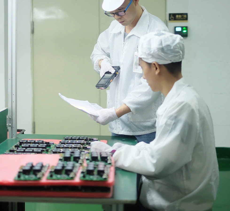
Continuous monitoring is what separates a burn-in test from a bake. The rack should monitor supply current, at least one functional output per board and the board temperature, and it should log the values rather than only alarm on them. A board that draws 20 percent more current than its neighbours from hour three is a candidate failure, and without logging it will only be discovered at the end of the run.
Set alarm thresholds from the qualified baseline rather than from the data sheet. The current drawn by a good board depends on the firmware, the temperature and the component tolerances, so the threshold has to come from a sample of known good units run on the same rack. Where a parameter drifts gradually, trend it rather than alarming, since a slow drift over 48 hours is usually a rack or a chamber effect rather than a board defect. Decide in advance what happens when an alarm occurs. Removing a board mid run invalidates its stress record, so the procedure should state whether the board is replaced, whether the position is left empty or whether the run is aborted. Leaving a position empty changes the chamber loading, which changes the temperature for every other board in the run.
Recording and Classifying Failures
Failures during burn-in are the main output of the test, so failure recording and classification decide whether the test is useful at all. Separate failures that occur in the first hour, which are almost always handling or contact faults, from those that occur later, which are more likely to be genuine early life failures. Record the time to failure, the monitored parameter that moved first and the board temperature at that moment.
Keep the failed boards for analysis rather than scrapping them immediately. A failure that repeats on a second run in the same position points at the rack; the same board failing in a different position points at the board. That single comparison resolves most disagreement about whether the burn-in test is generating false failures, and it requires nothing more than storing the unit and the record together. Summarise the run with the yield, the failure rate per thousand hours, the temperature spread across positions and the number of rack interventions. Those four numbers, tracked over successive runs, show whether the process is stable and whether the test is screening or merely adding cost.
Rack Maintenance and Requalification
Racks need a maintenance schedule and requalification against a known good board. The schedule should cover contact inspection and cleaning, harness continuity measurements, fan and airflow checks, and verification of the monitoring channels against a reference load. Each task should have an acceptance value rather than a visual judgement, and the results should be filed with the rack identification.
Requalify the rack whenever its wiring changes, whenever a monitoring channel is repaired, and at a defined interval such as annually. Requalification means running a known good board and a board with a known injected fault, and confirming that the rack passes the first and detects the second. A rack that cannot detect a known fault has lost its purpose, and no amount of temperature data will reveal that.
FAQ
What temperature should burn-in be run at? Set the chamber from the junction temperature you intend to reach, not from a habit. Calculate the rise from power dissipation and thermal resistance for the hottest device, and confirm by measurement. Charging the chamber to 125 C when the intended junction temperature is 100 C will create failures that the test itself caused.
How many boards can a burn-in chamber hold? Treat loading density as a controlled parameter. Fill the chamber to the maximum that still holds the temperature spread within about 5 C across all positions, and compute the total power dissipation against the chamber rating at the set point rather than at ambient.
Why do some boards fail in burn-in and pass on retest? Failures in the first hour are usually contact or handling faults rather than board defects, which is why time to failure has to be recorded. Repeat a suspicious failure in a different rack position: a failure that follows the board is a board problem, and one that stays in the same position is a rack problem.