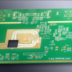
Electromigration: 5 Design Rules for Long Life
Electromigration is the movement of metal atoms in a conductor that carries current. The electrons push atoms along the trace, slowly thinning the metal upstream and piling it up downstream. The process is slow, but it never stops, and a trace that is designed on the edge of its capability will eventually open or grow a hillock that touches a neighbour.
It matters most where features are small and currents are high. A power trace on a thick copper board is rarely at risk, while a fine trace inside a package substrate or under a large via can reach the limit in a few thousand hours of operation at temperature.

What Electromigration Does to a Conductor
The driving force is the momentum transfer from moving electrons to the metal lattice, and it acts in the direction the current flows. Atoms accumulate at the end of a line and are depleted at the beginning, so the damage is not uniform along a trace but concentrated at the ends and at any change of geometry.
A change of geometry means a corner, a via, a junction or a step in width. Those points carry a local current density that is higher than the rest of the trace, and they are the places where a wear-out failure appears first on a life test.
Current Density and the Design Limit
Current density is current divided by cross sectional area, and it is the quantity that the design rules limit. The usual figures are given in amperes per square millimetre or per square mil, and they already include an allowance for the temperature rise that the trace will see in service.
Two traps are common. The first is using the average current instead of the peak, which ignores the inrush of a motor or the charging pulse of a capacitor bank. The second is using the nominal width instead of the width after etching, which on a fine trace can be a fifth of the pattern width.

Temperature Rise Is the Other Half
The rate of migration rises steeply with temperature, so an extra twenty degrees can shorten the life of a trace by more than an order of magnitude. Temperature rise and current density are therefore not separate checks: a hot board has to be designed with a lower density limit than a cool one.
Heat comes from the trace itself, from neighbouring traces, from a component and from the environment. The self heating of a trace is calculated from its resistance and its current, and that figure should be added to the ambient the board will actually see, not the ambient of the test bench.
Via Geometry and the Weak Point
A via is the tightest part of most current paths, because its barrel is thin and its interface with the trace is a step in area. Current crowds into the corners of that step, and a partially filled or badly plated via can have an effective area far below its nominal size.
The design response is to use more than one via for a high current path and to keep the connections symmetric, so that no single barrel carries a disproportionate share. Where a via sits directly under a solder joint, the joint itself becomes another interface in the same chain and should be assessed with it.
Copper Grain, Plating and Impurities
Metal moves more easily along grain boundaries than through the lattice, so a plating process that produces fine grains with a high boundary area will migrate faster than one that produces large columnar grains. Additives and brighteners in the bath are the practical controls on that structure.
Impurities act in both directions. Some raise the activation energy and slow the process, while others, notably a poorly controlled level of certain metals, will accelerate it. Our copper plating notes describe how the bath parameters are held in a production line.
Void Formation and Open Circuits
Void formation is the visible result. Atoms leave a region faster than they arrive, a hole opens in the metal, and the local current density rises because the remaining area is smaller. The process then accelerates, which is why an electromigration failure looks sudden even though it was growing for months.
An open circuit at the end of the sequence is a field failure that is hard to diagnose, because the site is under a component and the trace looks intact from outside. Sectioning a failed board is the only way to confirm the mechanism, and the alternative is a misdiagnosis of assembly damage.
Test Coupons and Accelerated Life
A coupon with a narrow trace, four point connections and a known width is the standard vehicle for the test. Current is raised and the board is held at a controlled temperature until the resistance rises by a set percentage, which is taken as the failure point.
The results from a small sample are extrapolated to service conditions using an acceleration model, and the extrapolation is only as good as the temperature measurement. Our thermal testing notes cover the measurement, and the coupon itself is designed like the ones used for impedance work.
Design Rules That Buy Margin
The rules that help are simple and additive. Increase the width where the current is high, split the current across parallel traces, keep the temperature down with copper area and thermal vias, and avoid sharp corners and abrupt width changes on a power path.
Where a trace cannot be widened, the current can sometimes be reduced by changing the duty cycle or the sequence of operation, which is a design change rather than a layout one. Both are cheaper than a field failure, and both should be recorded in the design file rather than left in a review note.
Manufacturing Choices That Affect Life
Plating thickness, grain structure and the cleanliness of the copper surface all move the result, and so does the surface finish where it forms an intermetallic with the alloy. A change of plating supplier is a change to the life of every power trace on the board.
The consistency of the process matters as much as its target. Our plating uniformity notes describe how the thickness is held across a panel, because a trace that is thin at one end carries a higher local density than the design calculation assumed.
Records and Lifetime Claims
A lifetime claim needs the coupon data, the acceleration model, the temperature used and the failure criterion. Without those four items the number cannot be compared with another supplier, and a purchase specification written on a different basis will produce two answers to the same question.
The record should also state what was not tested: a claim for a signal trace says nothing about a via under a connector, and a claim at one temperature cannot be extended to a product that runs hotter. The IPC and JEDEC documents behind the test methods define the conditions that must be reported with the result.
FAQ
At what current does a trace become a concern? There is no single figure, because the limit depends on width, thickness, temperature and the required life. A narrow trace running warm can be at risk at a few hundred milliamps, while a wide trace on thick copper carries several amps without complaint.
Does a wider trace always solve the problem? It reduces the current density, which is the main lever, but it does nothing for a local hot spot or a poorly plated via in the same path. The whole current path should be designed together rather than one section at a time.
How is a failed joint distinguished from a migration open? By sectioning the board and looking at the metal. Migration leaves voids and a characteristic grain structure, while assembly damage leaves a crack or a lifted pad, and the two look quite different under a microscope.