Solder Bridge: 5 Rules to Stop Bridging
A solder bridge is a connection where there should be none, formed when enough molten alloy joins two adjacent pads or pins to make an electrical path. On a fine pitch assembly it is the defect that ends the panel, because a bridge on a signal net can change the whole function of the board before anyone has looked at it.
The cause is always excess alloy in the wrong place, but the alloy arrives there by different routes. Paste volume that is too high, a stencil design that delivers it inconsistently, a reflow that lets the deposit collapse sideways and a wave solder process that drags solder between pins all produce the same result at inspection.
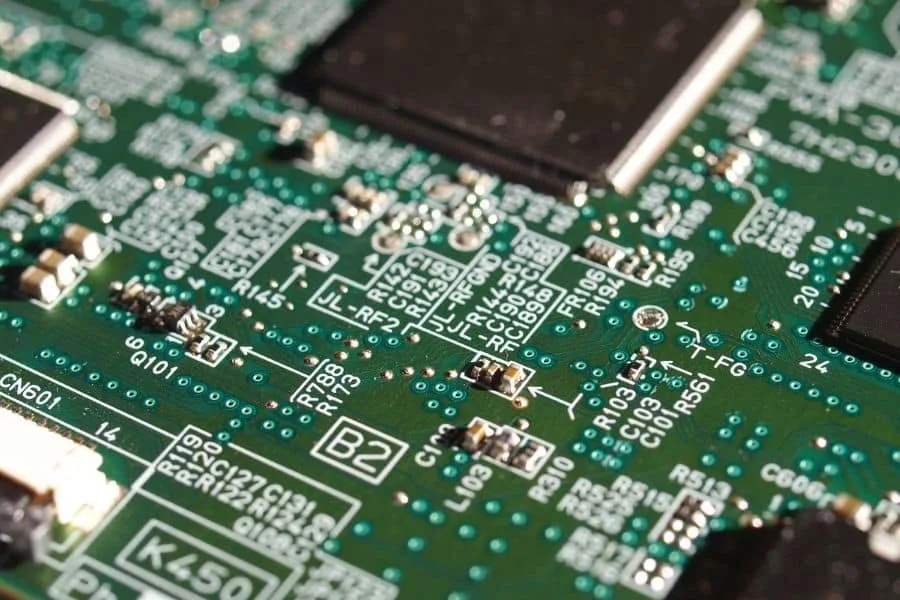
What Makes a Solder Bridge
Molten solder moves toward the hottest surface and stays where surface tension is lowest. Two pads separated by a narrow mask dam are still connected by a path of air and flux, and if enough alloy is present, the surface tension of the mass is lower when it is joined than when it is split. The bridge then survives cooling.
That means the window between a good joint and a bridge is narrow wherever pads are close together. The distance between the pads, the height of the mask dam between them and the amount of alloy delivered all set how narrow that window is, and the printer controls the last of the three.
Paste Volume and Aperture Design
Deposits that are too large collapse into each other before the alloy even melts, particularly where the stencil is thick or the aperture extends past the pad. Aperture dimensions should follow the pad, and the aperture should be reduced slightly where fine pitch parts are involved, since transfer efficiency already works against the printed volume.
Volume consistency matters as much as volume. Two adjacent deposits that differ in height will slump toward each other during the ramp, and the taller one provides the alloy that forms the bridge. The paste volume record is therefore the first place to look, and the spread across the panel matters more than the average.
Stencil Thickness and Area Ratio
A thicker stencil delivers more alloy for a given aperture, which is helpful for a pin in a large hole and harmful between two fine pitch pads. Thickness should be chosen for the finest feature on the panel, and where one panel carries both heavy and fine features, a stepped stencil is a better answer than a compromise on thickness.
Area ratio sets whether the aperture fills and releases at all. Where the ratio is low, the printer compensates by slowing down or by raising pressure, and both changes push more paste onto the surface of the stencil. That surface paste is then pressed between the stencil and the mask, which is exactly how a bridge begins. The stencil tension also affects how cleanly the foil separates from the mask surface.
Printer Settings That Reduce Bridging
Squeegee pressure that is too high forces paste under the stencil and into the gap between adjacent apertures. Pressure should be the lowest value that still cleans the stencil, and the change should be made with the printed volume measured rather than judged from the appearance of the panel.
Speed and separation control how the paste behaves at the moment of release. A slow squeegee stroke fills the aperture from the bottom and leaves less on the surface, while a fast separation pulls a string of paste out of the aperture. The blade itself also matters, since a worn or damaged metal squeegee leaves an uneven film that builds up along the length of the print stroke.
Placement and Component Alignment
A component that is placed off centre leaves a larger gap on one side of each terminal and can press paste out from under the other. That displaced paste becomes the bridge, particularly on packages with a small pitch. Placement offset should be measured and kept inside a fraction of the pad width.
Where the part is placed after the paste has started to dry, the paste does not flow back into the aperture footprint, and the deposit stays displaced. The time between printing and placement is therefore part of the bridge control, and it should be limited for fine pitch panels rather than left to the flow of the line.
Reflow Profile and Slump
Paste slumping before the alloy melts is a common bridge mechanism. A slow, hot preheat gives the paste more time to spread sideways across the mask, and a too-fast ramp causes the solvent to boil and push the deposit outward. The profile should follow the paste supplier’s recommendations rather than a general purpose curve.
Flux activity also matters. A flux that is fully activated wets the pads and pulls the molten alloy into place, while a flux that is exhausted before the peak leaves the alloy where it is. The exposed pad case shows the same effect at a larger scale, where a poorly activated flux leaves the alloy spread across the pad instead of forming a fillet.
Wave Solder Bridging
Wave solder produces bridges by a different route. The alloy leaves the wave as a film between two pins and solidifies before it can drain, usually where the pin pitch is small or where the board leaves the wave at an angle that holds the film in place. Exit angle, conveyor speed and board support all influence whether the film breaks.
Flux plays a larger part here than in reflow. A flux that is applied unevenly leaves some pins without enough activity, and the alloy will not pull back to the pad. Preheating matters too, since a board that reaches the wave cold draws heat out of the alloy and changes the drainage. The solder skip settings on a selective machine are a useful reference for the way exit conditions change the result.
Mask Dam and Pad Geometry
The mask dam between two pads is the physical barrier that a bridge has to cross. A dam that is too narrow for the mask process will be partly removed during development, and the remaining ridge is not tall enough to stop the alloy. Dam width should be specified with the mask registration tolerance in mind, not as an ideal value.
Pad geometry contributes as well. Pads that extend beyond the component termination give the alloy a place to collect, and a solder thief can be used deliberately to pull excess alloy away from a fine pitch row. Where a thief is used, it has to be connected to a net that can accept the material, which is a design decision rather than a process one.
Inspection, Rework and Records
Bridging is detected by optical inspection and confirmed by electrical test. Optical inspection finds the visible bridge, while test finds the one buried under a component, so the two should be treated as complementary. The inspection lighting should be checked against a known bridge sample so that the defect is proven to be visible.
Rework of a bridge should remove the excess alloy without damaging the mask or the pads underneath, and the method should be qualified for the pitch involved. Records should capture the pad references involved, because a bridge that repeats on the same two pads points to a design or stencil issue while a bridge at random positions points to the printer.
FAQ
Why do bridges appear only on some panels? A bridge that comes and goes is usually a paste volume problem rather than a stencil problem. Deposits that are consistent across the panel print consistently, so the appearance of the defect at random positions points to transfer variation, paste drying or a drifting print stroke.
Does reducing paste volume stop bridging? It helps when the deposit is the source of the excess alloy, and it is usually the quickest change to try. The reduction has to stop at the point where the joint still meets the fillet requirement, so the volume should be reduced in steps with the printed result measured after each one.
Can a bridge be removed without reworking the component? Where the bridge is between two accessible pads and there is room to work, the excess alloy can be wicked away and the joint reflowed locally. Where the bridge sits under a package or inside a fine pitch row, the risk of damage usually makes a full removal and refit the more predictable option.