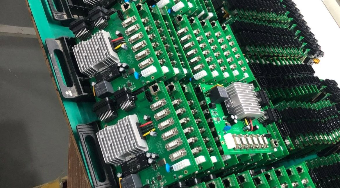
Reflow Cooling Rate: 6 Rules for Strong Solder Joints
Reflow cooling rate is the speed at which a board leaves the molten state, and it is the part of the profile that receives the least attention. The ramp up is watched closely because it protects components, while the ramp down is often whatever the oven does when the heat is switched off. It is written into the profile and rarely verified on the product.
That is a mistake, because the cooling rate decides the grain structure of the solidified solder. Cool quickly and the grains are fine; cool slowly and they grow, and the joint that results is softer, more prone to voiding and less able to survive thermal cycling.

What the Reflow Cooling Rate Changes
Solder freezes through a range rather than at a single temperature, and the reflow cooling rate decides how long the alloy spends in that range and how much the grains can grow. A slow pass through the freezing range produces coarse dendrites; a fast pass leaves a fine, more uniform structure.
The same window also controls how the joint relieves stress. A fast cool locks in a small amount of stress with a strong structure, while a slow cool allows the joint to relax into a shape that reflects the surface tension rather than the joint design.
Why the Ramp Down Is Often Ignored
The zone that follows the peak is usually just a cooler section of the oven, and its set point is chosen for throughput. Unless the profile is measured with a thermocouple attached to the board, nobody knows what the actual reflow cooling rate is. A profile qualified on one product does not transfer to another with a different thermal mass.
The measurement method matters, because the cooling rate measured on the board surface differs from the rate in the oven atmosphere, and the difference grows on a dense assembly. The attachment practice used in reflow thermocouple attachment is what makes the number real.
Grain Structure and Joint Strength
A fine grain structure resists the movement of dislocations, so it is stronger and harder than a coarse one of the same alloy. That difference shows up as better fatigue behaviour under thermal cycling, especially on joints that are small or heavily loaded.
Grain structure also affects the intermetallic layer that grows at the interface. The growth is diffusion controlled, so time at temperature is what matters, and a long slow cool extends the time during which that layer keeps thickening.
Voiding and Cooling
Voids form when flux vapour or entrapped gas cannot escape before the solder solidifies. A slow cool gives the vapour more time to leave, while a fast cool can trap what is still inside and freeze it in place.
The balance depends on the paste and the thermal mass of the joint. Where voiding is a problem, the answer is usually to improve the ramp up and the soak so that less gas remains at the peak, rather than to slow the cool and risk a coarse structure. Void acceptance limits are covered in work on void acceptance criteria.
Cooling Rate and Component Stress
Components see the cooling rate as thermal shock, and the risk rises with the difference between the coefficient of expansion of the body and the board. A fast ramp down is harder on large ceramic parts and on packages with a stiff body. Small chip parts tolerate a fast ramp far better than a large module on a stiff substrate.
The rate should be chosen as a compromise between metallurgy and component limits. Most shops keep the ramp down fast enough to produce a fine structure and slow enough that the worst component on the board stays inside its specification.
Setting the Cooling Zone
Cooling is controlled by the zone set points after the peak, the conveyor speed and, on some ovens, by active cooling fans or a water cooled section. Fans and heat exchangers also need cleaning, because dust reduces the achievable rate quietly. Changing any one of them changes the profile, so they should be recorded together as a single setting.
The practical target is a straight, controlled line from the peak to solidus rather than a curve that flattens near the end. Zone temperature and conveyor speed are adjusted together, in the same way the settings used for cooling rate control are tuned on the line.
Measuring the Rate on the Board
The profile should be measured on a board that carries the same copper distribution and the same component mix as production, with the thermocouple attached to a representative joint. A bare test board gives a rate that is wrong in both directions.
The cooling rate is normally reported in degrees per second between the peak and a temperature below the solidus, and it should be stated with the interval that was used. The interval is part of the result rather than a detail. Where the process follows a published method, such as the assembly guidance from IPC, the definition in that standard should be applied.
Interaction With Other Profile Zones
Cooling does not stand alone. A hot peak followed by a fast cool produces a different joint from a cool peak followed by the same ramp, and the soak that precedes the peak decides how much flux activity is left for the joint to clean itself, so a change made to fix one defect can affect another.
Where the profile has been tuned for other reasons, such as paste performance, the cooling section should be re-checked rather than assumed. The same care used for print parameters and for reflow atmosphere belongs in the ramp down.
Records, Qualification and Drift
The record should carry the full profile, the cooling rate with its interval, the conveyor speed, the paste lot and the result of the joint inspection. With that, a change in joint appearance can be traced to a profile change rather than to a material.
Ovens drift, and a cooling fan that has lost efficiency or a filter that is blocked will change the ramp down without changing any set point. The profile should be re-measured on a schedule and after every maintenance activity, and the joint strength checks used in ball shear and pull testing give the numbers to compare. Trending the rate over time shows oven drift before a defect appears.
FAQ
What cooling rate should a reflow profile use? Most processes target a controlled ramp down in the range of a few degrees per second from peak to solidus. The exact value follows the paste supplier and the component limits, and it should be measured on a real assembly.
Does a faster cool always give a stronger joint? Up to a point. A very fast cool improves the grain structure but increases thermal shock on the components and can trap voids, so the limit is set by the parts on the board as much as by the metallurgy.
Why is the measured rate different from the oven setting? The oven setting describes the atmosphere, while the board responds to its own thermal mass. Dense boards and heavy copper planes cool more slowly than the zones suggest, which is why the profile is measured on the product.