Component Height and Clearance Verification
Component height is a mechanical parameter that decides whether an assembly can be built at all, and it is usually verified with a drawing rather than with a measurement. A part that is 0.3 mm taller than its nominal value can collide with a placement nozzle, block airflow in the reflow oven, or stand above the conformal coating film that is supposed to cover it.
Clearance work starts with data rather than with hardware. The bill of materials should carry a maximum height for every part, the assembly drawing should show the envelope that the housing allows, and the two should be compared before the first panel is loaded rather than after the first collision.
Why Height Data Matters
Nominal height is not enough for clearance work, because the tolerance is what causes collisions. An electrolytic capacitor specified at 10 mm may be supplied at 10.5 mm from one manufacturer and 9.5 mm from another, and both parts meet their own drawing.
The maximum value is the one that belongs in the clearance stack. Where a supplier does not publish a maximum, the value should be measured on a sample from each lot, and the measured maximum should be used for the envelope calculation rather than the typical figure from the data sheet. A stack calculated from typical values has no margin at all, because every part in it can sit at its maximum at the same time.
Sources of Height Data
Three sources are available: the component drawing, the measured value from a sample lot, and the value read by the placement machine or the AOI system. The third is the least accurate for absolute height, because optical systems measure the top surface rather than the seating plane.
A height measurement should be taken from the seating plane to the highest point, with the part seated on a flat surface rather than on a solder pad. Where the component placement requirements allow a small tilt, the measurement should include the effect of that tilt on the overall envelope.
Placement Nozzle and Feeder Clearance
The nozzle travels over components that are already placed, so the machine needs clearance around every part that is loaded after the tallest one. A common failure is a large inductor placed early with a nozzle that passes over it later in the program.
Feeder clearance is a separate check. A tall reel or a deep tray can obstruct the head when it travels to the far end of the machine, and the collision is a mechanical event that damages the nozzle rather than the board. Both checks belong in the program review before the product is released to the line. A dry run at reduced speed, with the head travelling over a sample board, is the cheapest way to confirm them.
Shadowing in Conformal Coating
Coating shadowing is the direct consequence of height. A spray travels in straight lines, so the area behind and beneath a tall part receives less material than the open board surface, and the film that forms there may be too thin to insulate.
The effect is measurable. Where the coating specification calls for a minimum thickness, the shadowed areas are the ones to measure, since the film beside a tall part is often the thinnest on the whole assembly, and the <a href="https://www.gopcba.com/conformal-coating-coverage-inspection/” title=”coating coverage inspection”>coating coverage inspection method should include the board area beside the tallest components rather than only the open areas.
Reflow Airflow and Thermal Shadowing
A tall part disturbs the airflow across the board and changes the heat transfer to everything downstream of it. The result is a thermal shadow in which joints sit several degrees below the rest of the assembly, and the difference grows with part height and with airflow velocity.

A shadow of 5 °C is usually tolerable, while 15 °C is not, because the cold joints will not reach the minimum peak temperature while the exposed ones are already at their upper limit. Reducing the conveyor speed helps the cold area but pushes the hot area further toward its limit, so the practical fix is a profile with a longer plateau rather than a higher peak.
Coplanarity Against Height
Coplanarity describes how well the terminations of a package lie in one plane, while height describes where the body sits. The two are measured differently and are often confused, because a package that is tilted shows a height variation across its own body as well as a coplanarity error at its leads.
For area array devices, the coplanarity figure is the one that decides whether the part will connect, and the coplanarity inspection result should be read together with the measured seating height, since a part that sits high will have thin joints even when its balls are perfectly flat. The two measurements answer different questions: coplanarity says whether contact is possible, while height says how much solder the joint can hold.
Inspection and Verification
Height is verified at three points in the flow: incoming inspection on a sample lot, first article on the assembled board, and final inspection before packing. The first confirms the part, the second confirms the process, and the third confirms that nothing was pushed out of position afterwards.
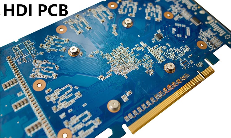
The automated optical inspection system can be used for the second and third checks when it has a height channel, and the limits should be set from the drawing envelope rather than from the height of a good sample board.
Handling Tall Components
Tall parts are also fragile parts. A connector standing 15 mm above the board is a lever, and any handling force applied to its body is multiplied at the solder joints, which is where the damage appears later as a cracked fillet.
Handling rules should name the tall parts explicitly, with support points identified on the drawing. Depanelisation, board carriers and test fixtures should all be checked against the height map, because each of them applies a force that the joints were not designed to take.
Records and Release Criteria
The release package should contain a height map with maximum values, the housing envelope, the nozzle and feeder clearance check, and the measurement results from the first article. Where any of the four is missing, the assembly is being built on an assumption rather than on data.
Changes are the main risk to that package. A supplier change, a substitution approved by purchasing, or a revised housing drawing can each break the envelope, so the height map should be re-checked whenever any of those three events occurs, and the re-check should be recorded.
FAQ
Which height value should be used for clearance checks? The maximum across all approved suppliers, including the effect of tilt, because the nominal value will not protect the nozzle, the housing or the coating film.
How much airflow shadowing is acceptable in reflow? A difference of about 5 °C between shadowed and open joints is comfortable, while 15 °C usually means the profile must be reshaped or the panel layout revisited.
Is AOI height data accurate enough for the envelope check? It is accurate enough to detect an unexpected part or a misplaced one, but absolute height should come from a measurement taken at the seating plane rather than from an optical top surface reading.