




Dry Film Exposure Energy: Reading the Step Wedge
Exposure energy is the amount of light that reaches the resist during imaging, expressed in millijoules per square centimetre. It decides how completely the resist reacts, and therefore how well it survives development and how faithfully it defines the pattern.
The difficulty is that the number is not visible on the panel. A board exposed with too little energy still develops, and one exposed with too much also develops, and the difference appears later as an undercut line or as a residue that will not come off. Neither condition is visible on the imaged panel without a measurement, and both are discovered at the etcher or at electrical test.
What Exposure Does to the Resist
A negative dry film is a polymer that cross-links where light reaches it. The cross-linked areas become insoluble and stay on the copper after development, while the unexposed areas are dissolved away to open the pattern.
The reaction needs a threshold dose, and the degree of cross-linking depends on the energy above that threshold. Below the threshold the film is soft and partly soluble, and above it the film becomes hard, slightly brittle and progressively more difficult to strip later.
Measuring Energy With a Step Wedge
A step wedge is a film with 21 patches of increasing density, imaged onto the panel at the same time as the product. After development the highest numbered patch that is still present tells the operator where the exposure sits, and the number is compared with the target band for the resist.
The wedge converts an invisible dose into a visible number, and it also shows the uniformity of the exposure across the panel, because the wedge can be repeated at several positions. A typical specification is to hold seven to nine steps on the standard wedge, and the target band for a given resist is supplied with it. The band is wide enough to allow for process variation and narrow enough to catch a lamp that has lost output.
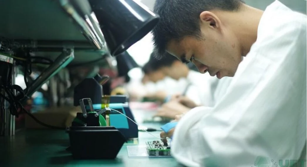
The Window Between Under-cure and Over-cure
Under-cure leaves the resist soft at the edges of the image, so development attacks the sidewall and the line comes out narrower than the artwork with a sloped profile. The consequence is a line that etches wider than intended, and a fine feature that lifts during development.
Over-cure closes the small openings and leaves a scum of partially soluble resist in the features, which resists the developer and then resists the etchant. The visible result is an open circuit where a fine gap should be, and the cause is usually found only when the step wedge is checked. The panel itself usually passes inspection at the imaging stage and fails after etching.
Development and Its Interaction With Energy
Development removes the unexposed resist, and its strength, temperature and dwell all interact with the exposure. A stronger developer can compensate for a slightly under-cured film, and that compensation is usually a mistake, because it also attacks the sidewalls of the good features.
The two stages should be controlled separately. Development is also sensitive to its own temperature, and a bath that has warmed by five degrees behaves like a stronger solution. Development is set to the standard for the resist and the film thickness, and exposure is set from the wedge, so that a change in one does not silently hide a change in the other. The relationship between resist and etching is described in the notes on dry film lamination and its effect on the imaged pattern.
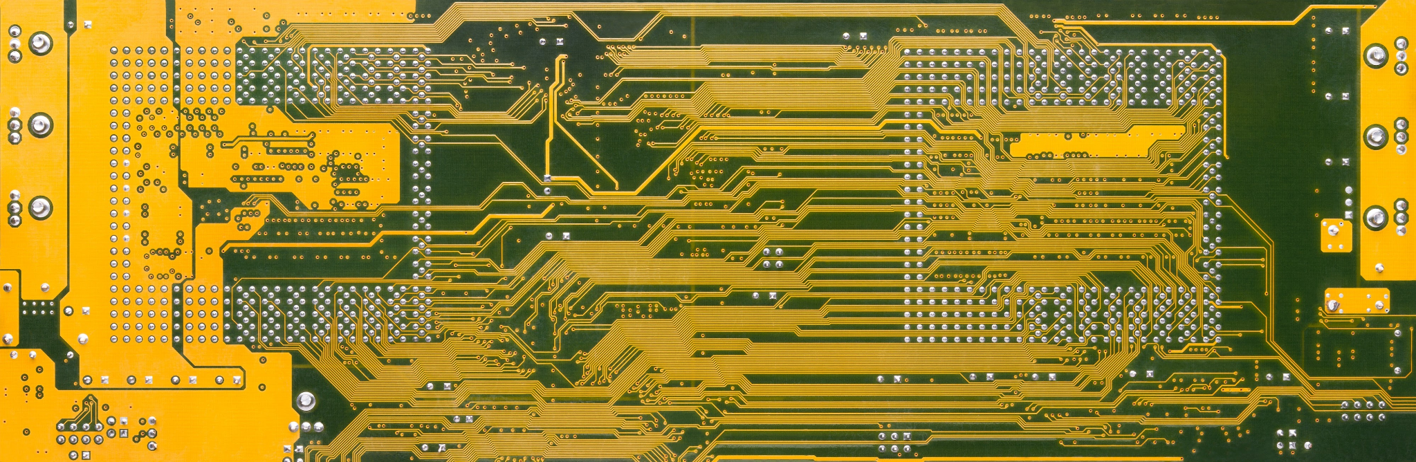
Line Width and Sidewall Angle
A correctly exposed and developed film has an almost vertical sidewall, and the line width on the copper after etching matches the artwork within the process tolerance. As exposure falls, the sidewall slopes and the etched line widens, and as exposure rises, the walls pinch inwards.
Measuring the imaged resist line before etching separates the imaging problem from the etching problem. That measurement is quick on a microscope and it is the only way to know whether the line width error was created at exposure or at the etcher, which is the same distinction described in the notes on etch factor and line width.
Exposure Machine Uniformity and Lamp Age
Lamps lose output as they age, and the loss is gradual enough to pass unnoticed until the wedge shows it. A lamp near the end of its life can still expose the centre of the panel while the edges fall below the threshold, which produces a pattern that varies with position. The variation is often invisible on a small test coupon and obvious on a production panel.
Uniformity is quoted as a percentage across the usable area, typically within plus or minus 10 percent, and it is measured with a radiometer at several positions. The radiometer reading and the wedge result should be recorded together, because the wedge reports the effect and the radiometer reports the dose. The comparison of resist types is covered in the notes on wet film and dry film resist.
Resist Thickness, Type and Sensitivity
Thicker resist needs more energy, because the light has to penetrate further before it reaches the copper. A 40 µm film therefore needs a higher dose than a 25 µm film of the same chemistry, and the two cannot share a setting.
The spectral sensitivity of the resist also has to match the lamp, and a film designed for one wavelength band will not perform at the same dose under a different source. Where a resist is substituted, the exposure window has to be re-established from the wedge rather than carried over. The same applies after a lamp change, even when the replacement is identical in type.
Verification on Production Panels
The step wedge belongs on production panels, not only on test pieces. A wedge placed in a corner of each panel, or at a defined frequency such as once per shift, is what proves the exposure throughout a lot rather than at a single moment.
The result should be recorded against the lot with the lamp hours and the radiometer reading. Where a wedge falls outside the target band, the usual response is to check the lamp and the radiometer rather than to adjust the conveyor speed, since speed affects dwell while the lamp affects intensity, and the two have different effects on the sidewall. Adjusting speed to recover a wedge number leaves the actual cause in place.
Records and Drift Detection
The records that matter are the wedge result, the radiometer reading, the lamp hours, the resist type and thickness and the developer parameters. Trends in those numbers show a lamp ageing or a developer drifting before the product is affected.
A sudden change usually means a lamp replacement, a resist lot change or a chemistry problem, while a gradual change means ageing. Recording the numbers makes that distinction possible within a shift, and it is what turns the exposure step from a setting into a controlled process. The verification principles that follow are the same as those applied in fine line etching control.
FAQ
How is exposure energy measured in production? With a step wedge imaged on the panel and a radiometer at the exposure plane. The wedge shows the result on the resist, and the radiometer shows the dose at the surface.
What happens if the exposure is too low? The resist is soft at the edges, development undercuts the sidewall and the etched line comes out wider than the artwork, with fine features at risk of lifting.
Does development strength compensate for low exposure? It can hide the problem, and it does so by attacking the sidewalls of correctly exposed features. Set development to the standard for the resist and set exposure from the wedge.


1 Comment
Laser Ablation For Solder Mask Openings: Depth And Edge Quality
[…] and a definition requirement if they are controlled. The imaging route is described in the notes on exposure energy, and the alternative deposition route in the notes on solder mask […]