PCB Guide Hole Control: Tolerances for Panel Alignment
Guide hole control is about the tooling holes that hold a panel in place while it is drilled, laminated, imaged or routed. When they are right, the panel drops onto its pins with a light push and every layer lines up. When they are wrong, every operation downstream inherits the same error. A panel that does not sit flat on its pins will be drilled at an angle as well as in the wrong place.
The holes are small and cheap, which is exactly why they get neglected. A guide hole a fraction too large can shift a panel by more than the registration budget allows, and the defect it causes looks like an inner layer short rather than a tooling problem. Panel alignment starts here.
What a Guide Hole Has to Do
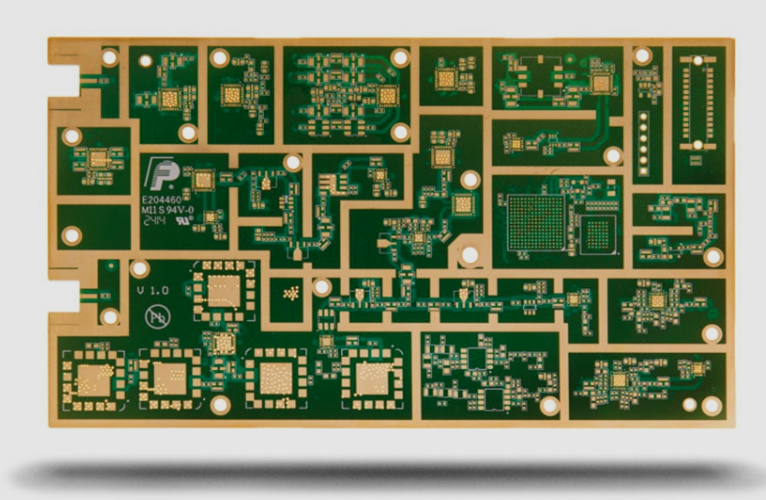
A guide hole has to locate a panel on a pin without letting it move and without making the panel hard to load. It carries no electrical function, so it can be placed wherever the tooling needs it, which makes it the most flexible feature on the board.
Most shops use two or three tooling holes. Three fix rotation as well as position and stop a panel being loaded the wrong way round, while two allow the panel to be reversed unless the pattern is deliberately made asymmetric. The pattern should also be kept clear of the panel centre, where the circuit is densest and a hole would cost routing space.
Diameter and Pin Clearance
The finished diameter is chosen to match the tooling pin with a small clearance. Too little clearance and the panel binds, so the operator forces it and the hole wears; too much and the panel rattles, so each operation starts from a slightly different position. Both faults are felt by the operator as an annoyance and by the process as a loss of registration.
Pin clearance should be given in the drawing as a range rather than a single size, because drill wear and plating both change the finished hole. On a plated panel the guide hole is normally left unplated so that its size stays predictable over the life of the tool.
Position Accuracy and Tolerance
The guide holes must be positioned from the same datum as the circuit pattern, not from the panel outline. If the outline is routed later and the holes were placed from it, the pattern inherits the routing tolerance and the two errors add instead of staying independent.
The tolerance on hole position is usually tighter than the tolerance on the circuit itself, because a hole error is multiplied by the distance from the pin. The work described in PCB layer registration control rests on this number.
Registration Through the Process
Every step that uses a pin has its own tolerance, and the errors accumulate along the route. Drill, lamination, exposure and routing all reference the guide holes, so a hole that moves during lamination moves the image for every later step as well. A hole that has been reamed or damaged in one step therefore carries that error with it to the end of the line.
Registration is therefore managed as a chain rather than as a single operation. Measuring where each step places the pattern relative to the holes turns a vague complaint about misregistration into a specific step to fix.
Routing and Depaneling Tooling
Routing programmes use the guide holes to set the origin, so a worn hole shows up as an off centre cut. The bit wear described in depaneling router bit wear guidance is only one of the variables, because a good bit in a badly located panel still cuts outside the tolerance.
Where the panel is separated by a router, the tooling holes should sit outside the finished outline so that they survive until the last cut. A hole that is swallowed by the rout leaves the final cut without a reference.
Wear, Burrs and Damage
Guide holes wear because panels are pushed on and pulled off thousands of times, and the wear is not uniform. A hole that has opened up on one side will bias the panel consistently in that direction, which is harder to see than random scatter. Wear also grows faster on the loading side, so the hole becomes oval rather than round over time.
Burrs at the hole edge are a second problem. A burr holds the panel off the pin by a small amount, and that offset tilts the panel enough to matter on a fine line board. The rules for spacing and rail geometry in panel rail design set the space that keeps the tooling clear of the circuit.
Guide Holes in Assembly Fixtures
The same holes are often reused for assembly fixtures, stencil printing and depaneling jigs, which puts them under pressure from several owners. A hole that is fine for a drill machine may be too large for a precise stencil printer that needs a tighter fit.
Where the requirement conflicts, the tighter use should set the tolerance and the other stations should be given a locating insert or a bushing. A bushing is replaceable, so it absorbs wear that would otherwise be taken by the panel itself. The bushing should be checked on the same schedule as the hole, since it takes the wear the panel would otherwise see.
Inspection and Measurement
Guide holes should be measured on the finished panel, not only on the artwork. Diameter, position and roundness are the three numbers that matter, and a simple pin gauge plus a vision measurement covers all three without a dedicated fixture. The measurement should be taken at the same temperature as production, because laminate and metal move at different rates.
Trending those numbers over a production lot shows wear before it becomes a defect. Once a gauge begins to drop through a hole that it used to grip, the tool has reached the end of its useful life and should be replaced on schedule rather than on failure.
Records and Change Control
The drawing should state the hole size, the position tolerance, the datum and the plating condition, and the tooling list should name the pins that match. A change of pin supplier or of panel size is a change to the tooling and should be qualified rather than assumed equivalent. The same applies to the tooling plate, which wears in the same way the holes do but is replaced far less often.
Where the shop works to a published standard, such as the tooling guidance from IPC, that reference should be quoted in the work instruction. The spacing rules in panelization spacing rules and the separation methods in mouse bite depaneling work both depend on the guide holes being where the drawing says they are.

FAQ
How many guide holes does a panel need? Two are enough to fix position and three to fix rotation as well. Three is the safer choice because it prevents a panel being loaded the wrong way round.
Should guide holes be plated? Usually not. Leaving them unplated keeps the finished diameter predictable, since plating thickness varies and would change the fit against the tooling pin.
What causes a panel to sit off centre on the pins? Wear, burrs or a hole that has opened up on one side. Measuring the hole on the finished panel and trending it over the lot identifies the cause before it becomes a defect.