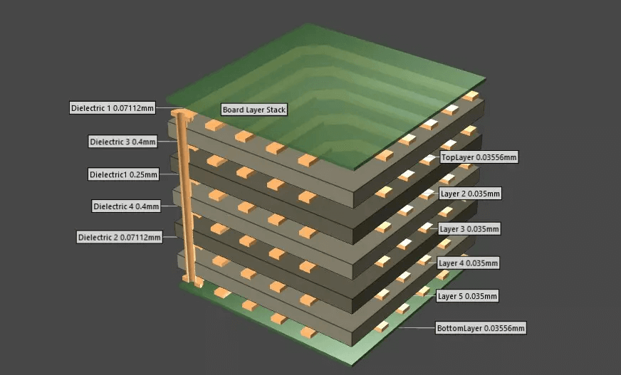
Board Thickness Variation Control in Lamination
Board thickness variation is a lamination problem that surfaces as an electrical one. A panel that is 0.08 mm thicker at one corner than at another will show a different dielectric thickness on the same layer, and a controlled impedance design that was simulated with a single value will not be met across the whole panel.
The total thickness of a multilayer board is the sum of the cores, the prepreg and the copper, minus whatever resin flows out of the stack during pressing. Controlling the variation therefore means controlling the press as carefully as the material.
Where Thickness Variation Comes From
Four sources dominate: variation in the incoming laminate, variation in the prepreg resin content, the copper distribution on the layers being pressed, and the pressure and temperature profile of the press itself. Each contributes a different amount to the final spread.
Incoming material sets the floor. A core that is specified at 0.10 mm with a tolerance of plus or minus 10 percent already consumes 0.02 mm of the budget, so the tolerance should be compared against the board specification before the stack-up is fixed. Where the sum of the individual tolerances exceeds the board tolerance, the stack-up has to change before the press is adjusted at all.
Resin Flow and Fill
Prepreg is a glass cloth impregnated with partially cured resin, and the resin flows during the press cycle to fill the gaps around the copper. How much flows depends on the resin content, the pressure and the temperature at which the pressure is applied.
Too little flow leaves voids and a thin dielectric over dense copper, while too much leaves the stack starved and thinner than designed. Both appear as thickness variation, which is why the press cycle design is tied to the copper pattern rather than to the panel size alone. The window between these two failures is narrow on a heavy copper design and wider on a signal layer with light copper.
Press Cycle and Cooling
The press cycle has three parts that matter for thickness: the heat ramp, the dwell under pressure and the cooling phase. Pressure applied too early pushes resin out before it has softened, while pressure applied too late allows the stack to cure without filling the pattern.

Cooling is the part most often neglected. A stack that is removed while still hot continues to relax and can spring back unevenly, so the cooling rate and the temperature at unloading should be specified, and the copper balance and warpage behaviour of the same stack records whether the cycle is producing a flat panel. A press that is opened early also releases volatile material that has not finished reacting, which appears later as delamination after reflow.
Dielectric Thickness and Impedance
Dielectric thickness is the parameter that matters electrically. Impedance falls as the dielectric becomes thinner, so a variation of 10 percent across a panel translates into a measurable shift in the characteristic impedance of a controlled line.
Where the design is impedance controlled, the stack-up should state the target dielectric thickness per layer with a tolerance, and the supplier should confirm it from the pressed panel rather than from the nominal build. The stack-up dielectric thickness record is the document that ties the two together.
Copper Distribution Effects
Copper takes up space that the resin would otherwise occupy, so a layer with a large ground plane presses thinner than a layer with isolated traces. On a panel where one area is dense and another is open, the finished thickness follows the same pattern.
Thieving bars and balanced copper distribution reduce the difference, but they cannot remove it entirely. Recording the copper balance per layer alongside the thickness measurement makes that characteristic visible rather than mysterious. Where a design has an unavoidable imbalance, the stack-up should be built with that in mind and the resulting thickness variation should be stated as a known characteristic rather than treated as a defect.
Measuring Thickness
Thickness is measured with a micrometer at defined points on the panel, or by a microsection where the individual dielectric layers have to be resolved. The instrument should be checked against a reference block at the start of each session, since a micrometer that has drifted will make a good panel look out of tolerance. Micrometer readings are fast and give a map of the panel, while a section gives absolute values for one location.

Both methods should be used together: the micrometer map shows the spread, and the section shows whether the spread comes from the core, the prepreg or the copper. Measuring before and after pressing, with the same instrument and the same operator technique, is what makes the numbers comparable, and the lamination process record should state the instrument used.
Corrective Action on the Press
A thickness that is uniformly outside the target is a build issue and is corrected by changing the prepreg combination. A thickness that varies across the panel is a press issue and is corrected through the pressure, the plate flatness or the temperature uniformity.
The two are easy to confuse because both show up in the same measurement. Measuring several points on the same panel separates them, and a panel that is uniformly wrong but consistently so should be examined before any press adjustment is made. Where the variation follows the position of the panel in the press, the plates and the press pads are the first items to inspect.
Acceptance Criteria
Acceptance should state the total board thickness range, the dielectric thickness tolerance per layer for impedance controlled designs, and the allowed variation across a single panel. Without the third value, a board can meet its overall tolerance and still fail the electrical requirement. The overall figure is what the assembly drawing usually quotes, while the electrical requirement is met by the layer values.
The criterion should also name the measurement locations, since the thickness at the panel edge next to a thieving bar is not the same as the thickness over a dense ground plane in the middle. Standard locations give a result that can be compared between panels and between suppliers.
Records and Trend Monitoring
Records should carry the laminate lots, the prepreg lots with their resin content, the press cycle identification and the thickness measurements with their locations. With those fields, a shift in the process can be tied to a material lot rather than to the press.
Trending the panel spread over time is the most useful view. A widening spread with a stable mean points to material variation, while a moving mean points to the press cycle, and the two call for different corrective actions before the next impedance measurement fails.
FAQ
What causes board thickness variation across a panel? Uneven resin flow during pressing, non-uniform copper distribution, variation in the incoming laminate and prepreg, and temperature or pressure differences across the press platens.
How does thickness variation affect impedance? A thinner dielectric raises the capacitance per unit length and lowers the impedance, so a 10 percent thickness change across a panel produces a measurable shift on a controlled line.
Should thickness be checked before or after pressing? Both. Pre-press measurements confirm the build, and post-press measurements confirm the result, and comparing the two shows whether the variation came from the material or from the press.