X-ray Oblique Views: Seeing What a Top-Down Scan Misses
X-ray inspection produces a shadow, and a shadow of a ball grid array taken from directly above hides a great deal. The balls overlap, the package substrate masks the top of each joint and a joint that has lifted from its pad can look exactly like one that has not.
An oblique view removes part of that ambiguity by tilting the geometry so that the joint is seen at an angle. It is the cheapest addition to an X-ray programme, and it is the difference between a system that confirms what is already suspected and one that finds defects on its own.
What a Top-Down X-ray Shows
A transmission image records the total attenuation along the path of the beam, so everything above and below a feature contributes to the picture. For a BGA, the copper pad, the solder ball, the package substrate and any thermal via under the pad are all superimposed in one projection.
That is adequate for solder voids, because a void is a region of low attenuation inside a known joint, and it is adequate for gross bridging. It is much weaker for joint separation, because a gap of a few tens of micrometres changes the attenuation far less than the thickness variation of the ball itself.
Why a Lifted Ball Can Hide
A joint that has separated at the pad leaves a crack or a gap in the plane of the pad, and a beam travelling vertically passes through that gap in line with the rest of the joint. The attenuation along the path changes only slightly, and the image looks normal.
The classic case is the head-in-pillow defect, where the ball and the paste have not merged and the boundary sits horizontally inside the joint, which is one way a reflow open presents itself. Seen from above it is invisible; seen at an angle it appears as a line within the ball, and the joint can then be confirmed by sectioning.
How an Oblique View Is Produced
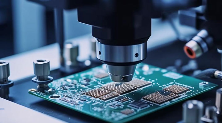
Two arrangements are used. In the first, the board is tilted on a stage while the source and detector remain in place, which changes the projection angle of everything on the board equally. In the second, the source or the detector is moved off axis, which achieves a similar effect without moving the product.
Tilting the product is mechanically simpler and is what most bench and in-line systems do for occasional checks. The stage has to be rigid, because a board that shifts during the exposure blurs the image in exactly the way that hides a small gap. Moving the beam off axis is faster and avoids the risk of the board shifting, and it is the usual choice where the view is needed on every unit.
Tilt Angle and What It Reveals
Most separation defects are visible at a tilt of 30 to 45 degrees, and a larger angle improves contrast while it also increases the thickness of material the beam must cross. Beyond about 60 degrees the image degrades because the path through neighbouring joints becomes long.
The angle should be recorded with the image, because a separation seen at one angle may be invisible at another. For a ball of 0.4 mm diameter, a gap of 20 µm subtends a useful angle only when the geometry is favourable, and the operator needs experience to choose it. A short reference list of angles for each package type removes most of that judgement.
Magnification, Resolution and Depth of Field
Oblique views demand more from the geometry than top-down scans do. Magnification has to be high enough to resolve the gap, typically a few hundred times for a fine pitch array, and the depth of field has to cover the vertical extent of the joints being compared.
Resolution is set by the source size and the detector, and a microfocus tube with a spot of a few micrometres gives the sharpest image, with the conventions for reporting it described in the notes on void measurement method. A system that is optimised for throughput rather than resolution produces images in which a real separation is indistinguishable from noise. Resolution is also quoted at the centre of the field and degrades towards the edge, so a defect near the corner of a large panel is harder to see.
Oblique Versus Computed Tomography
A single oblique view is a projection, so it still superimposes the structure along the beam. Computed tomography reconstructs the volume and removes that problem entirely, at the cost of a scan that takes minutes rather than seconds and produces data that has to be reviewed slice by slice.
The two are complements rather than alternatives. Oblique views are used for screening and for confirming a suspicion on a production unit, while tomography is used for failure analysis and for establishing what a defect actually looks like before the screening criteria are written.
Reading the Image Without Over-Reading It
An oblique image is easy to over-interpret, because the changing path length creates contrast that can look like a defect. The rule is that a separation is called only when it appears in two views taken at different angles and its position is consistent with the joint geometry.
Operators also need a boundary sample. A set of known good and known bad assemblies, imaged at the production settings, prevents both the false call and the missed defect, in the same way that a boundary sample protects any visual inspection. The set is re-imaged whenever the system is serviced, because a change in the tube or the detector changes the appearance of everything.
When to Use It in Production
Oblique imaging is slower than a top-down scan, so it is normally applied to a defined subset: the first articles of a build, boards from a process that has just changed, and units that have failed a functional test at temperature. Those are the cases where a hidden separation is most likely and where the extra inspection time is easiest to justify.
For products where the consequence of a hidden separation is severe, the view can be taken on every unit at a lower magnification as a screen, with a second, closer look reserved for anything that appears marginal. The decision should be written into the inspection plan rather than left to the operator.
Records and Correlation With Sections
Each oblique image should be stored with the angle, the magnification, the system settings and the unit serial number. When a defect is later confirmed by sectioning, that pair of images is the reference that tells the next operator what the defect looks like on this product.
The correlation is the part that is usually missing. A shop with a library of confirmed images and their angles makes far better decisions than one that interprets each image from first principles, and the library costs nothing beyond the discipline of keeping it. The measurement conventions for the void work that accompanies it are set out in the notes on X-ray void measurement.
FAQ
Why can a broken joint look perfect from above? Because the gap lies in the horizontal plane, and a vertical beam passes through it in line with the rest of the joint. The attenuation along the path changes too little to see.
What tilt angle should be used? Thirty to forty five degrees covers most separations. Beyond about sixty degrees the beam crosses too much neighbouring material and the image degrades.
Does an oblique view replace cross-sectioning? No. It is a screening and confirmation tool that shows where to cut, and the section remains the evidence when a defect has to be argued.