Entry Burr Control in PCB Drilling: Causes and Removal
An entry burr is the ring of copper pushed up around the rim of a hole where the drill enters the board. It forms because the drill lifts the copper foil as it cuts through, and the material has nowhere to go except upwards around the shank. A small burr is normal; a large one interferes with plating, with solder mask and with the seating of a component, and it is one of the first signs that a drill is worn.
What an Entry Burr Is
The burr is a raised lip of copper and laminate at the hole entrance, continuous or broken around the circumference. It has to be distinguished from the drill exit burr on the opposite face, which forms for different reasons and is controlled by the backup material rather than by the entry.
The size of the burr is described by its height above the surface and by whether it is attached or loose. A loose fragment is more damaging than an attached one, because it can travel, lodge under a component or contaminate a plating bath, and it is often found far from the hole it came from.
How the Burr Forms
Three mechanisms contribute. The first is plastic deformation of the copper as the drill point pushes material ahead of it before the cutting edges engage. The second is the lifting action of the margin as the drill passes, which drags copper upwards along the wall. The third is thermal, when a dull drill heats the copper enough to soften it.
The balance between them depends on the drill geometry, the spindle speed and the feed. A sharp drill with the correct point angle shears the copper cleanly and leaves a small burr; a dull or wrongly ground drill pushes the material instead of cutting it, and the burr grows quickly with hit count.
Entry Material and Its Role
Entry material sits between the drill and the board and takes the initial impact. A thin, hard aluminium foil holds the copper down as the drill enters and produces a small, tidy burr; a soft or missing entry material allows the copper to lift freely and produces a larger one.
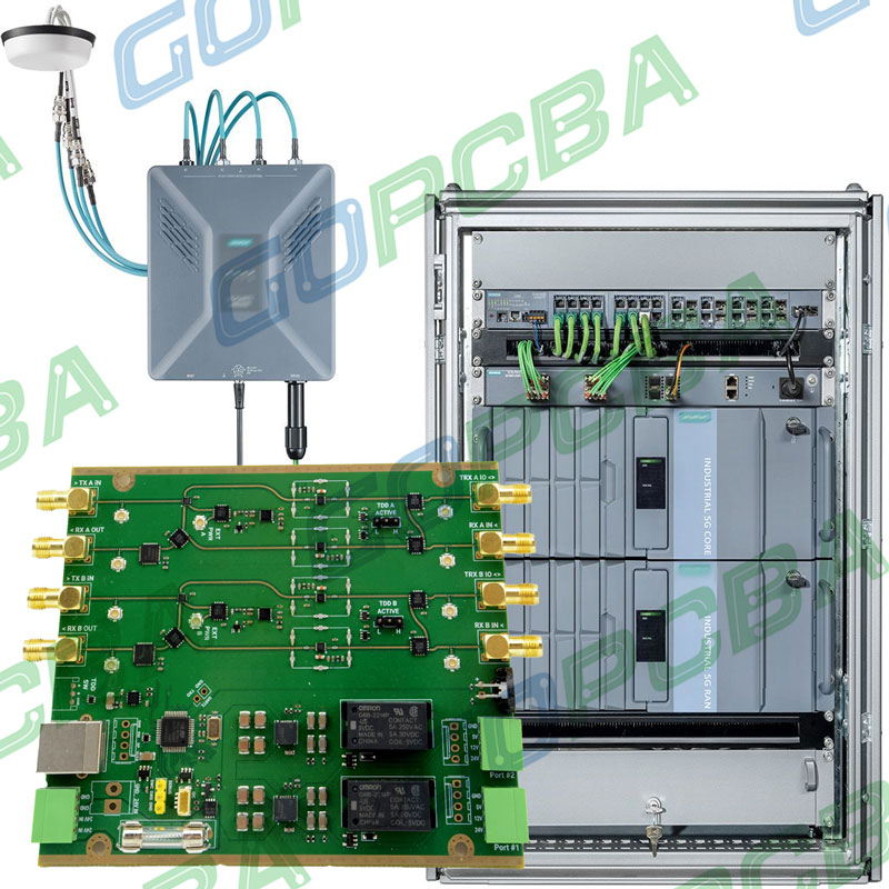
The entry material also lubricates and cools. A foil with a lubricating coating reduces friction on the margin, which reduces both the heat and the dragging action. Choosing the entry material together with the drill parameters is the standard way to control burring and hole quality at the same time, and the same material affects the backup material selection at the exit side.
Drill Wear and Burr Growth
Burr height is one of the most sensitive indicators of drill wear, and it usually changes before hole size or wall quality do. Tracking burr height against hit count gives a direct measure of the point at which a drill should be replaced or reground.
The relationship is not linear. Burr height stays low through most of a tool’s life and then rises sharply as the cutting edge rounds. The transition is the useful signal, and it is why a regrind policy based on measured burr height is more reliable than one based on a nominal hit count alone.
Parameters That Reduce Burring
Feed rate has the largest single effect. A feed that is too light rubs the surface and pushes copper ahead of the drill, while an adequate feed engages the cutting edges immediately. Most shops find the burr decreasing as feed rises until the point at which the drill begins to deflect and the hole quality falls.
Spindle speed changes the heat input. High speed with a light feed is the worst combination for burring, because it generates heat without cutting. The speed should be chosen so that the surface speed at the drill diameter suits the laminate, and it should be reduced as the drill gets smaller.
Deburring Methods
Where a burr cannot be controlled at the drill, it is removed mechanically. A brush deburring machine with an abrasive roller removes the raised material from the surface without attacking the hole wall, provided the roller pressure is set correctly. Too much pressure breaks the corner of the hole and rounds the pad edge.
Alternative methods include a light sanding pass, a high-pressure water jet and a chemical deburring step. Each has to be followed by a cleaning operation, because the material removed has to leave the board before plating. Where the burr is removed by brushing, the brush itself wears and must be replaced on a measured schedule rather than on appearance.
Measuring and Accepting a Burr
Burr height is measured with a microscope at an oblique angle, with a dial indicator, or by examining a section through the hole rim. The measurement should be taken at a defined number of holes per panel and after a fixed hit count, so that the values are comparable between lots.
Acceptance is normally expressed as a maximum height, for example 25 micrometres on a 35 micrometre foil, and as a requirement that no loose material is present. A burr that projects into the hole is treated separately, because it reduces the finished hole diameter and can affect the plated hole dimensions after plating.
Interaction With Plating and Soldering
A loose burr that reaches the plating bath becomes a particle, which produces a nodule on the plated surface and can short a fine pattern. An attached burr at the hole rim creates a step that the plating follows, so the copper thickness at the entrance is uneven and the hole may be partially closed.
At assembly the consequences appear as solder mask that will not lie flat at the rim and as solder that flows over the burr rather than into the joint. Both problems are usually attributed to the mask or the soldering process until the rim is examined under magnification.
Records and Process Control
The record should carry the drill type and hit count, the entry and backup material, the feed and speed, and the measured burr height with the number of holes examined. Those fields make it possible to see whether a change in burring came from the tool or from the process.
Burr height is worth plotting as a trend rather than as a pass or fail figure. A gradual rise across several lots points to a change in drill supplier or in laminate, while a step change points to a specific event such as a regrind or a change of entry material. The trend turns a quality complaint into a maintenance schedule, and it gives the shop a figure to quote when a customer asks how burring is controlled.
FAQ
What causes an entry burr in PCB drilling? Plastic deformation of the copper as the drill enters, dragging of copper by the drill margin and softening from frictional heat. A dull drill and a light feed are the two most common contributors.
Does entry material reduce burring? Yes. A hard foil holds the copper down as the drill enters, and a lubricated coating reduces friction on the margin. Removing the entry material increases burr height immediately.
How is a burr removed? By brush deburring, light sanding, a water jet or a chemical step, followed by cleaning. Brush pressure has to be controlled, because excessive pressure rounds the pad edge and damages the hole corner.