Flex Coverlay Bonding: Lamination Without Trapped Air
A coverlay is the flexible equivalent of a solder mask, and it is bonded to the finished circuit as a separate layer rather than printed as a coating. It carries an adhesive on one side, and the lamination cycle has to flow that adhesive around the conductors and into the clearances without trapping air. The bond is formed under heat and pressure, and its quality is decided before anyone can see the result.
The process differs from rigid board lamination because the materials are thin, the adhesive has to travel a long way relative to the layer thickness, and the finished part will be bent. A defect that would be cosmetic on a rigid board becomes a crack in a flex circuit. The relevant defects are voids and blisters, and both are process results rather than material properties.
What a Coverlay Does
The coverlay protects the conductors from the environment, from handling and from the bending the product is designed for. It also defines which areas are exposed, because its openings are what allow a connector or a component to be attached. An opening cut in the wrong place exposes a conductor that should have been covered.
The adhesive flows into the spaces between conductors, and how completely it fills them decides the flexibility of the finished area. An area with air trapped between conductors has an effective stiffness and a local stress concentration. The same area also decides where the circuit will fail first when it is cycled.
Coverlay Construction
A coverlay is a polyimide film coated with a B-staged adhesive and supplied with a release liner. Its film thickness, its adhesive thickness and the tack of the adhesive are the three properties the process depends on. The liner protects the adhesive until the moment of alignment and has to be removed without stretching the film.
The thickness is chosen with flex life in mind, because the neutral axis of a bent circuit moves with the relative thicknesses of coverlay and base material. Storage and shelf life for this class of material are described in the notes on prepreg and laminate storage. A base material and a coverlay of similar thickness place the copper close to the middle of the stack.
Adhesive Flow and Fill
Lamination pressure and temperature make the adhesive flow, and the flow has to be sufficient to fill the clearances and to bond the film to the substrate. Insufficient flow leaves voids and unbonded areas that fail in bending. The clearances between conductors are where the adhesive has the most distance to travel.
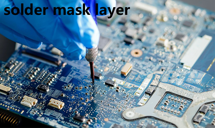
Excessive flow removes adhesive from where it is needed and can push material into the openings. The window is narrow, because the same variable that fills the gaps also empties the edges, and it is set by experiment on the actual pattern. Squeeze out at the panel edge is the visible sign that the flow was on the high side.
Lamination Cycle and Pressure
The cycle has a ramp, a dwell and a cool down, and each affects the result. The ramp sets how quickly the adhesive softens, the dwell sets how far it flows and how completely it cures, and the cool down sets the stress locked into the bond. A long dwell at a high temperature cures the adhesive and lets it flow for longer at the same time.
Pressure is applied through a press pad, and the pad has to be flat and compliant enough to follow the copper pattern. A worn pad transfers the same pressure unevenly and produces areas of poor bonding, as described in the notes on tooling plate maintenance. A pad used many times takes a permanent set that the next cycle cannot correct.
Trapped Air and Blisters
Air is trapped when the adhesive front closes around a pocket before the air can escape. The usual sources are a fast ramp, a vacuum applied too late, and a pattern with a closed clearance that has no path to the edge. A clearance that reaches the panel edge gives trapped air a route out and is easier to fill.
Blisters then appear after the cycle or after a later soldering operation, when the trapped air expands. The defect is often attributed to the base material rather than to the lamination, because it shows up at assembly rather than at fabrication. The same mechanism explains a blister that appears only on boards that pass through a second reflow.
Registration and Openings
The coverlay has to be registered to the conductors with a tolerance smaller than the smallest opening, and the openings themselves are formed by routing, by laser or by punching. Each method leaves a different edge and a different tolerance. The method also decides whether the opening has a burr that can lift during bending.
Registration is affected by the dimensional change of the coverlay during lamination. A material that shrinks differently in the two axes rotates the pattern, and the error grows across a large panel. Registration is measured on coupons at the panel corners rather than at the centre.
Bend Radius and Flex Life
Flex life is set by the strain in the copper when the part is bent, and that strain depends on the bend radius and on the position of the copper relative to the neutral axis. Coverlay thickness moves the axis.

A thin coverlay and a thick base move the neutral axis away from the conductors and reduce the strain, while the opposite arrangement increases it. Stack design rules are described in the notes on layup symmetry control. The design rule is therefore a rule about the complete stack rather than about the coverlay alone.
Inspection and Acceptance
Inspection covers bond quality, blisters, adhesive squeeze out and the condition of the openings. A visual check finds surface defects and says nothing about the bond quality beneath an opaque film. Squeeze out that reaches a pad is a functional defect rather than a cosmetic one.
Where the bond has to be verified, a peel test on a coupon or a cross section on a sample is used. Both are destructive, and both are run on a panel processed with the production batch. A result from a panel laminated in a different cycle describes that cycle and not the production one.
Records and Process Control
The record holds the coverlay material and its lot, the adhesive thickness, the cycle, the pressure and the registration result. With those fields a blister can be attributed to the cycle or excluded from it. A change of coverlay supplier is a change of process and should be qualified with a peel test.
The material also has a shelf life and a storage condition, and an expired roll behaves differently from a fresh one. The cycle itself is one of a family of lamination schedules, and those schedules are compared in the notes on lamination cycle parameters.
FAQ
Can a blister be repaired after lamination? It can sometimes be re-laminated, and the repair rarely restores the original flex life in that area.
Does a thicker coverlay improve protection? It improves abrasion resistance and reduces flexibility, because it moves the neutral axis away from the conductors.
Is a visual check enough to accept a bonded coverlay? No. It shows the surface and not the bond beneath an opaque film, so a peel or a section is needed to confirm adhesion.