Daisy Chain Continuity Coupons for Assembly Reliability
A daisy chain coupon is a test vehicle in which the joints of interest are wired in series so that the whole set can be monitored as a single electrical net. Instead of measuring thousands of joints individually, the test watches one resistance and reports whenever it changes. The technique is used for thermal cycling, for mechanical bending tests and for assembly process qualification.
The advantage is statistical as much as electrical. A single net that contains several hundred joints gives a direct measure of solder joint integrity across the whole population, and it does so without any probing that could disturb the sample. The limitation is that a change in the net does not say which joint failed, so the coupon is normally designed to be sectioned afterwards.
What a Daisy Chain Coupon Does
The coupon carries components and, in some designs, plated holes that are wired into a single loop. Current enters at one end and leaves at the other, so every joint in the path is in series with every other joint. A break anywhere in the loop produces the same electrical signature, which is a step change in the measured resistance. That is why the coupon is often described simply as a continuity coupon.
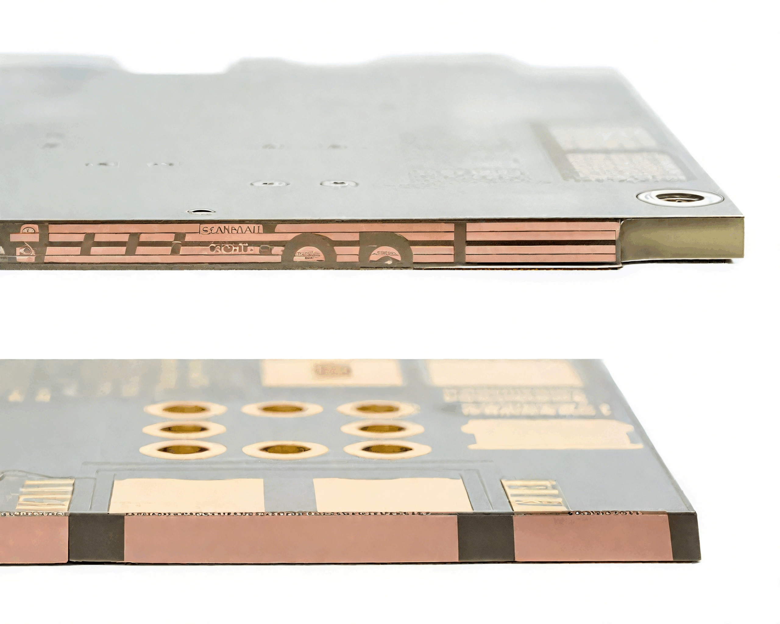
<img src="https://www.gopcba.com/wp-content/uploads/2020/12/service_02.jpg" alt="Daisy chain test coupon with routed traces between components” />
Because the joints are in series, the measured resistance is the sum of all of them plus the trace resistance. A change of a few milliohms in one joint is therefore difficult to see against a background of several ohms, which is why event detection is used rather than absolute measurement in most programmes.
Coupon Design and Routing
The routing should keep the trace resistance low and, more importantly, keep it stable. Wide traces on an outer layer change resistance with temperature, and a trace that runs close to a hot component adds drift that can look like a joint failure. The loop should be laid out so that the reference resistance is dominated by the joints rather than by the copper. A useful rule is to keep the trace contribution below ten percent of the total, which usually means short, wide links between adjacent pads.
Test points are placed at both ends of the loop so that the coupon can be probed or clamped by the monitoring equipment. Those points need to survive the test without wear, which is the same requirement that applies to any test point on a production board. They should also be placed so that the fixture does not load the coupon mechanically, because bending changes the joint stress during the test.
Choosing the Components
The component set should represent the package families that the process actually places. A coupon built only from large chip resistors will pass tests that a fine-pitch package would fail, because joint volume, standoff and thermal mass all differ between package types. A coupon that carries only one package family therefore validates that family and nothing else.
Where the coupon is used for thermal cycling, the components should also have thermal expansion behaviour representative of the product. A package that expands differently from the board will load the joints in a way that no amount of coupon design can compensate for.
Connection to the Monitoring Equipment
The coupon is connected to an event detector or a data logger through a fixture or a set of flying leads. The connection itself must be stable, because a moving lead produces exactly the same signature as a cracked joint. Where the coupon is cycled in a chamber, the leads should be strain-relieved and fixed to the fixture rather than allowed to move with the airflow.
Contact resistance at the fixture is a common source of false events. Gold-plated contacts and a light clamping force work better than a heavy clamp on bare copper, and the contacts should be cleaned or replaced on a schedule rather than only after a problem appears. Recording contact resistance at the start of each run gives a baseline that makes a later drift visible.
Event Detection Versus Resistance Measurement
An event detector samples the loop continuously and records any change above a set threshold, usually a small rise lasting longer than a defined time. That definition is what separates a genuine crack from electrical noise, and the threshold should be stated whenever a result is reported. A threshold that is too tight turns noise into events, while one that is too loose hides the first indication of a crack.
Resistance measurement is slower and more precise, and it is used where the failure criterion is expressed in ohms rather than as an event. The two methods answer different questions, and a programme that reports only one of them usually has to repeat the test to answer the other.
Baseline Recording and Screening
Every coupon should be measured before the test begins, and coupons with an unusually high or unstable baseline should be removed from the sample. Screening at the start removes the most common cause of a spurious early failure and costs almost nothing to perform.
The baseline should be recorded together with the fixture used and the ambient temperature, because a later comparison across fixtures is only meaningful when both are known. Coupons that are stored for a long period before use should be re-measured before the run begins. Storage in a humid room can raise the resistance of an unsealed coupon enough to matter.
Reading the Results
The output of a cycling programme is usually a plot of resistance against time or cycle number, with each event marked. A gradual rise followed by a step indicates a crack growing to full separation, while a series of isolated blips suggests a fixture or lead problem rather than a real failure.

Results are reported as the number of cycles to first event, and the distribution across the coupon population matters more than any single value. Failures that cluster in one package type or one location point to a process issue, while scattered failures point to the test setup. Where a new process is being qualified, the electrical result is normally supported by X-ray void data taken from the same joints.
Coupon Placement and Reuse
Coupons are usually built on the production panel, so that drilling, plating and assembly conditions match the product, and then separated before testing. Where the test coupon is a separate board, it should be assembled on the same line with the same stencil, paste and profile, or it measures a different process entirely.
Reuse is possible for coupons that carry only plated holes, provided they are inspected between runs and the baseline is re-measured. Coupons that carry soldered components are generally not reused, because the second reflow changes the joint microstructure that the test is meant to evaluate. Where reuse is essential, the baseline should be re-established and the previous cycle history recorded on the coupon itself.
FAQ
Why wire joints in series? So that a break anywhere in the set is detected by a single measurement channel, which makes continuous monitoring during cycling practical.
Does a daisy chain show which joint failed? Not by itself. The coupon is sectioned after the event to locate the failure, and the design should make that sectioning straightforward.
How many joints should a coupon carry? Enough to be representative, which in practice means hundreds of joints covering each package family used on the product.