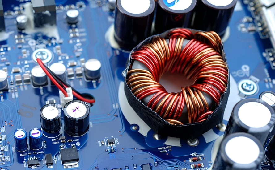
A UPS PCB is a critical electronic component within an uninterruptible power supply system. It manages power conversion, battery charging, monitoring, protection, and communication to ensure that connected equipment continues to receive stable power when the primary power source is interrupted.
An Uninterruptible Power Supply is designed to protect electrical and electronic equipment against power interruptions, voltage fluctuations, surges, and other power-quality problems. The PCB serves as the control and electrical interface between major UPS components, including batteries, rectifiers, inverters, sensors, cooling systems, displays, and communication interfaces.
Depending on the UPS architecture and power rating, the circuit board may perform different functions. These can include voltage regulation, battery management, inverter control, fault detection, thermal monitoring, overload protection, and communication with external monitoring systems.
Because UPS systems are frequently used for computers, networking equipment, industrial automation, medical equipment, data centers, and other critical loads, PCB reliability is essential to overall system performance.
Main Components of a UPS PCB
A typical UPS Circuit Board consists of multiple functional circuits that work together to manage power conversion and system protection.
1. Power Inverter
The inverter is one of the most important functional blocks in a UPS system. During a power outage, it converts the battery’s DC output into AC power suitable for the connected load.
The inverter control circuit regulates switching devices and helps maintain the required output voltage and frequency. In higher-power UPS systems, advanced semiconductor devices and sophisticated control algorithms may be used to improve conversion efficiency and response speed.
The inverter section must also be designed to manage switching losses, electromagnetic interference, thermal stress, and high-current paths.
2. Battery Charger
The battery charger maintains the battery at an appropriate state of charge so that backup power is available when required.
A charger circuit controls charging voltage and current according to the battery chemistry and charging strategy. Proper battery management helps prevent overcharging, excessive heat generation, and premature battery degradation.
In advanced UPS systems, the charging circuit may also monitor battery voltage, current, temperature, and operating status to improve battery life and system reliability.
3. Control Circuit
The control circuit acts as the central management section of the UPS PCB.
It continuously monitors input voltage, output voltage, load conditions, battery status, temperature, and fault conditions. When the input power becomes abnormal, the control system determines when and how the UPS should transfer to battery operation.
The control circuit may also manage:
- Overload protection
- Short-circuit protection
- Over-temperature protection
- Battery low-voltage protection
- Input and output voltage monitoring
- Fan control
- Alarm functions
- System diagnostics
- Communication interfaces
4. Integration with Other UPS Components
The UPS Circuit Board must communicate with other system components to provide coordinated operation.
Sensors can monitor temperature, current, voltage, and battery conditions, while alarms can notify users of abnormal operating conditions. Modern UPS systems may also communicate with computers, network management platforms, or industrial monitoring systems.
This integration enables real-time monitoring and helps maintenance personnel identify potential problems before they result in system downtime.
Common Types of UPS Systems
UPS systems are commonly divided into three major architectures: standby UPS, line-interactive UPS, and double-conversion online UPS. Each architecture provides a different level of power conditioning and protection.
1. Standby UPS
A standby UPS is one of the simplest UPS architectures. Under normal conditions, the connected load is supplied by the utility power source while the UPS monitors the input power.
When a power failure or significant abnormality is detected, the system switches to battery and inverter operation.
Standby UPS systems are generally suitable for less demanding applications such as personal computers, office equipment, and basic network devices.
2. Line-Interactive UPS
A line-interactive UPS uses a more advanced power-control architecture. It can compensate for certain voltage fluctuations without continuously relying on battery power.
An automatic voltage regulation (AVR) function can help correct moderate voltage sags or surges while reducing unnecessary battery cycling.
This architecture is useful in environments where voltage variations occur frequently but full online double conversion is not required.
3. Double-Conversion Online UPS
A double-conversion UPS provides a higher level of power conditioning.
Incoming AC power is converted to DC and then converted back to regulated AC power through the inverter. Because the load is continuously supplied through the conversion system, the output can be isolated from many disturbances on the incoming utility line.
This architecture is widely used for sensitive and mission-critical equipment, including data-center infrastructure, communication systems, industrial control equipment, and other applications requiring highly stable power.
UPS PCB Design and Manufacturing Considerations
Developing a reliable UPS PCB requires careful consideration of electrical, thermal, mechanical, and safety requirements.
UPS PCB Design Process
The PCB Design process normally begins with an analysis of the UPS power rating, input and output requirements, battery characteristics, environmental conditions, and protection requirements.
Engineers then develop the schematic and PCB layout using CAD tools. During this stage, component placement, current paths, grounding, thermal management, creepage and clearance, and electromagnetic compatibility must be considered.
Simulation and prototype testing can be used to evaluate electrical performance before volume production.
For high-power UPS systems, the layout should pay particular attention to high-current loops and high-frequency switching paths. Minimizing parasitic inductance and resistance can help improve efficiency and reduce switching noise.
Material Selection
High-Tg FR-4 is commonly used for many UPS PCBs because it provides good mechanical strength, electrical insulation, and thermal performance.
However, material selection should be based on the actual operating conditions. High-power or high-temperature applications may require materials with higher thermal resistance or other specialized properties.
The PCB copper thickness is also important. High-current power paths may require heavier copper or larger copper areas to reduce voltage drop and temperature rise.
For some high-power applications, advanced PCB structures or metal-core solutions may be considered when additional thermal performance is required.
Power Electronics PCB Layout
A UPS is fundamentally a power conversion system, so PCB layout has a major influence on efficiency, reliability, and electromagnetic performance.
The following factors should be carefully considered:
- High-current trace width and copper thickness
- Short switching-current loops
- Appropriate component spacing
- Creepage and clearance
- Low-inductance grounding
- Separation of power and control circuits
- Heat dissipation
- EMI reduction
- Safe routing around high-voltage areas
Sensitive control circuits should be isolated from noisy switching nodes whenever practical. Proper partitioning can reduce interference between power electronics and low-level control signals.
Surface Mount Technology and Assembly
SMT Assembly is widely used for compact UPS control boards because it supports high component density and automated production.
Surface-mount components can reduce board area and improve manufacturing consistency. Through-hole components may still be used for connectors, transformers, large capacitors, power devices, and other components that require greater mechanical or electrical strength.
The assembly process should include appropriate solder-paste printing, component placement, reflow soldering, inspection, and electrical testing.
For power electronics applications, solder-joint reliability is particularly important because repeated thermal cycling can create mechanical stress between components and the PCB.
Quality and Safety Standards
UPS products must meet applicable quality, electrical safety, EMC, and environmental requirements according to their intended application and target market.
The IEC 62040 series is an important reference for UPS systems, covering relevant safety, electromagnetic compatibility, and performance requirements.
Other requirements may include IPC manufacturing and assembly standards, applicable UL requirements, and RoHS restrictions.
The exact standards that apply depend on the final UPS product, market, voltage level, power rating, and regulatory requirements.
UPS PCB Testing
Testing is essential for verifying the reliability of a Power Electronics PCB.
Depending on the design, testing may include:
- Electrical continuity and isolation testing
- AOI inspection
- X-ray inspection
- Functional testing
- Thermal testing
- Temperature cycling
- Vibration testing
- High-voltage or dielectric withstand testing
- Overload testing
- Protection-function verification
- Battery charging and discharge testing
Testing should focus on both the PCB itself and its interaction with the complete UPS system.
Advanced Features of Modern UPS PCBs
Modern UPS technology is becoming increasingly intelligent. Advanced control systems can improve efficiency, monitoring capabilities, fault response, and maintenance.
Digital Signal Processing
Digital signal processors (DSPs) or microcontrollers can be used to control power-conversion processes with high precision.
Digital control enables the UPS to respond quickly to changes in input voltage, load conditions, and battery status. It can also support advanced functions such as waveform control, power-factor correction, protection logic, and system diagnostics.
As power electronics become more sophisticated, digital control is becoming an important part of modern Power Management systems.
Intelligent Cooling
Heat generation is a major concern in power electronics. Modern UPS systems may use intelligent cooling strategies to adjust fan operation according to temperature or load conditions.
Temperature sensors can provide feedback to the control system, allowing cooling capacity to be adjusted according to actual thermal conditions.
Effective thermal management can reduce unnecessary fan operation, lower energy consumption, and help extend component life.
Remote Monitoring and Management
Advanced UPS systems can communicate with external monitoring platforms through network interfaces or other communication protocols.
Remote management can provide information such as:
- Input and output voltage
- Load percentage
- Battery condition
- Remaining backup time
- Internal temperature
- Alarm status
- Maintenance information
- Fault notifications
This functionality is particularly valuable in data centers, communication networks, industrial facilities, and other environments where immediate access to the UPS may be difficult.
Common UPS PCB Problems and Troubleshooting
Although UPS PCBs are designed for long-term operation, component aging, thermal stress, electrical overload, environmental conditions, and other factors can cause failures.
Typical Problems
Common UPS PCB problems may include:
- Overheating
- Failed capacitors
- Damaged power semiconductors
- Fan failures
- Battery charging problems
- Voltage regulation problems
- Communication failures
- Faulty sensors
- Solder-joint degradation
- Firmware or control-system issues
These problems can cause unstable UPS operation, failure to switch to battery power, unexpected shutdowns, reduced backup time, or shortened battery life.
Diagnostic Tips
Troubleshooting should begin with a safe visual and electrical inspection.
Signs such as discolored components, damaged solder joints, swollen capacitors, burnt areas, or melted insulation may indicate excessive temperature or electrical stress.
Engineers can also measure voltage, current, and other electrical parameters at appropriate test points to identify abnormal circuit behavior.
UPS alarm codes and monitoring software can provide additional information about battery, temperature, overload, or inverter-related problems.
Because UPS systems can contain hazardous voltages and stored electrical energy, internal testing and repair should only be performed by appropriately trained personnel using suitable safety procedures.
Troubleshooting Steps
A basic troubleshooting process may include:
- Check external power and system connections.
- Verify battery status and battery connections.
- Review UPS alarm or fault codes.
- Inspect the PCB for visible damage.
- Check cooling fans and ventilation.
- Measure relevant electrical parameters using appropriate procedures.
- Verify firmware or control-system status when applicable.
- Replace damaged components only after identifying the underlying cause.
- Perform functional testing after repair.
If the fault involves high-voltage power circuits, damaged semiconductor devices, or complex control electronics, professional service should be used rather than attempting unsafe component-level repair.
Why Choose Kingda for UPS PCB Manufacturing?
UPS applications require reliable circuit boards because the PCB directly affects power conversion, monitoring, protection, and system control.
Kingda provides PCB manufacturing and assembly solutions for electronic applications with different structural and performance requirements. For UPS projects, a reliable manufacturing partner should be evaluated based on material selection, copper capability, manufacturing precision, assembly quality, engineering support, testing capability, and production consistency.
Early communication between the PCB designer and manufacturer is particularly important for power electronics. Design-for-manufacturing review can identify potential problems involving copper thickness, trace spacing, thermal management, drilling, component placement, and assembly before production begins.
For high-power UPS applications, the manufacturing process should also maintain strict control over PCB dimensions, copper distribution, plating quality, solderability, and assembly consistency.
Working with an experienced supplier such as Kingda can help customers develop PCB solutions that balance electrical performance, manufacturability, reliability, and cost.
Conclusion
The UPS PCB is the control and power-management foundation of an uninterruptible power supply system. It coordinates battery charging, power conversion, monitoring, protection, communication, and other essential functions.
Different UPS architectures—including standby, line-interactive, and double-conversion systems—place different requirements on the circuit board. As UPS systems become more powerful and intelligent, PCB design must address high current, high voltage, thermal stress, electromagnetic interference, component density, and long-term reliability.
A successful UPS PCB solution requires appropriate materials, optimized PCB Design, reliable SMT Assembly, effective Power Management, rigorous testing, and appropriate safety controls.
By considering these requirements from the early design stage and working closely with a capable manufacturing partner such as Kingda, UPS manufacturers can develop circuit boards that provide stable performance and dependable protection for critical electronic equipment.