Wire Bonding is an interconnection technology used to electrically and mechanically connect semiconductor dies, integrated circuits, substrates, or other electronic components to a package, PCB, or circuit substrate. Instead of using conventional solder joints, wire bonding creates connections with fine metal wires, commonly made from gold, aluminum, or copper.
The technology is widely used in semiconductor packaging, microelectronics, power electronics, sensors, MEMS, hybrid circuits, and specialized electronic assemblies. The appropriate wire material and bonding process depend on electrical requirements, pad metallization, operating temperature, mechanical requirements, cost, package structure, and long-term reliability.
A modern Wire Bonding Process is highly automated. Wire bonding equipment typically uses pattern-recognition systems to identify die bond pads, substrate features, and reference points. The machine then positions the bonding tool with high precision to create the required interconnections.
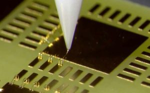
During bonding, the substrate or PCB must be securely fixed. Vacuum clamping or mechanical fixtures may be used to maintain planar stability and prevent movement. A capillary or wedge bonding tool guides the wire and applies the required force and energy to form the bond.
What Is Wire Bonding?
Wire bonding creates electrical connections between a semiconductor die and another conductive structure by using fine metal wires.
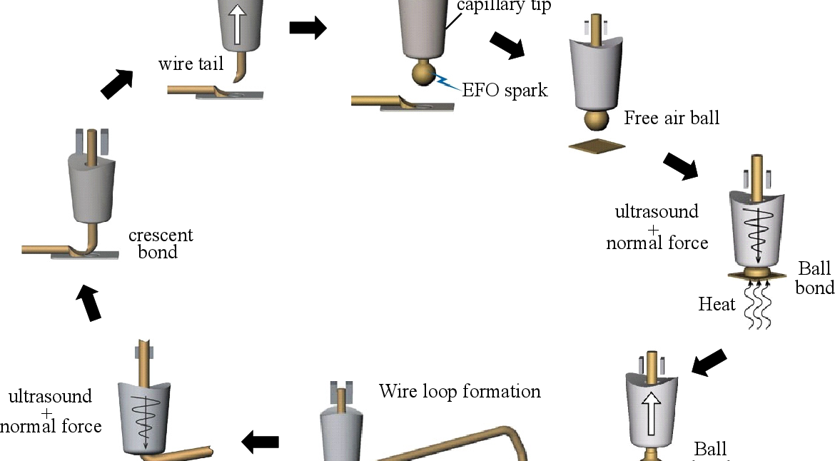
A typical wire bonding sequence involves:
- Positioning the substrate or PCB.
- Aligning the die and bonding pads.
- Feeding the bonding wire through the bonding tool.
- Creating the first bond.
- Forming a controlled wire loop.
- Creating the second bond.
- Cutting or breaking the wire.
- Repeating the process for all required connections.
- Inspecting the completed wire bonds.
The first bond is commonly formed on the semiconductor die, while the second bond connects to a substrate, lead frame, package, or other conductive surface. The exact sequence can vary depending on the bonding technology and package design.
Wire Bonding Materials
Material selection is one of the most important factors in wire bonding.
Gold Wire
Gold has historically been widely used because of its good bondability, corrosion resistance, and stable electrical characteristics.
Gold wire can be used in thermosonic bonding and is particularly common in applications where reliable fine-wire interconnections are required.
However, the relatively high cost of gold has encouraged manufacturers to evaluate alternative materials.
Aluminum Wire
Aluminum wire is commonly used with wedge bonding and is widely applied in power semiconductor and other specialized packaging applications.
Aluminum can be bonded at relatively low temperatures using ultrasonic energy, making it suitable for certain substrate and device structures.
Copper Wire
Copper offers high electrical and thermal conductivity and is increasingly used in semiconductor packaging.
Copper wire can provide electrical and thermal advantages, but it can also be more sensitive to oxidation and process conditions than some alternative materials. Appropriate process control, surface preparation, and bonding equipment are therefore important.
Silver and Other Bonding Materials
Depending on the application, silver and specialized wire alloys may also be used. Material selection should consider electrical conductivity, mechanical strength, corrosion behavior, bonding compatibility, thermal expansion, operating temperature, and cost.
Types of Wire Bonding
Several major bonding technologies are used in electronic manufacturing.
Ultrasonic Bonding
Ultrasonic Bonding uses mechanical ultrasonic energy to create a bond between the wire and the bonding surface.
The bonding tool applies force while ultrasonic vibration creates relative movement at the interface. This action disrupts surface contamination and oxide layers while promoting intimate contact between the bonding surfaces.
Aluminum wire and wedge bonding are commonly associated with ultrasonic wire bonding.
A simplified process includes:
- Position the wire over the bonding pad.
- Apply controlled bonding force.
- Apply ultrasonic energy.
- Form the first wedge bond.
- Create the required wire loop.
- Position the wire at the second bonding location.
- Apply force and ultrasonic energy to form the second bond.
- Clamp and break or cut the wire.
- Repeat the sequence for the remaining connections.
The actual bonding parameters depend on wire material, diameter, pad metallization, substrate material, tool geometry, and equipment characteristics.
Thermosonic Bonding
Thermosonic Bonding combines ultrasonic energy, mechanical force, and elevated temperature.
This method is widely associated with gold and copper wire bonding and is frequently used for semiconductor packaging.
A typical thermosonic process includes:
- Feed the wire through the capillary.
- Form the wire ball when ball bonding is used.
- Position the capillary over the first bonding pad.
- Apply force, ultrasonic energy, and controlled temperature.
- Form the first bond.
- Raise the capillary and create the wire loop.
- Move to the second bonding location.
- Form the second bond.
- Break or cut the wire.
- Repeat for the remaining connections.
For ball bonding, an electronic flame-off (EFO) system can be used to form a free-air ball at the end of the wire.
Thermocompression Bonding
Thermocompression Bonding uses heat and mechanical pressure without relying on ultrasonic energy as the primary bonding mechanism.
Heat, pressure, bonding time, surface condition, and tool geometry are important process variables.
Compared with thermosonic bonding, thermocompression bonding generally requires greater mechanical force and carefully controlled thermal conditions. It may be appropriate for specific package structures and materials where ultrasonic energy is undesirable or unnecessary.
Ball Bonding vs. Wedge Bonding
Wire bonding can also be classified according to the bonding tool and bond geometry.
Ball Bonding
Ball bonding typically uses a capillary tool and begins by forming a free-air ball at the end of the wire.
It is widely used with gold and copper wire and is common in semiconductor packaging.
Wedge Bonding
Wedge bonding uses a wedge-shaped bonding tool to press and bond the wire to the conductive surface.
It is frequently associated with aluminum wire and is often used for power devices and specialized applications.
The appropriate technology depends on pad layout, wire material, wire diameter, loop requirements, package construction, and electrical performance.
Wire Bonding Equipment
A modern wire bonder generally includes several integrated systems.
Pattern Recognition System
The pattern recognition system identifies die pads, substrate features, alignment marks, and other reference locations.
Accurate recognition is essential for fine-pitch wire bonding.
Bonding Head
The bonding head controls the movement of the bonding tool and wire.
It must provide precise positioning and repeatable force and energy application.
Capillary or Wedge Tool
The bonding tool determines how the wire is positioned and deformed during the bonding process.
Tool geometry has a direct influence on:
- Bond shape
- Bond size
- Loop profile
- Wire deformation
- Bond strength
- Pad interaction
Clamping and Fixture System
The substrate must remain stable throughout bonding. Vacuum fixtures, mechanical clamps, or customized tooling can be used depending on the product structure.
Key Wire Bonding Process Parameters
The quality of a PCB Wire Bonding process depends on controlling several variables simultaneously.
Bonding Force
Bonding force determines how strongly the wire is pressed against the bonding surface.
Excessive force can damage the bonding pad, create cratering, or deform the underlying structure. Insufficient force can result in weak or incomplete bonding.
Ultrasonic Power
Ultrasonic energy must be carefully controlled.
Excessive energy can damage the bond pad or wire, while insufficient energy may result in poor interfacial bonding.
Bonding Time
Bonding time determines how long the bonding energy and force are applied.
The acceptable range depends on the wire, pad, tool, and substrate.
Bonding Temperature
For thermosonic and thermocompression bonding, temperature is an important process variable.
The thermal profile should be controlled to avoid damaging the semiconductor, substrate, PCB, adhesive, or other temperature-sensitive materials.
Wire Loop Profile
The wire loop must maintain sufficient clearance from adjacent wires and structures.
An inappropriate loop profile can result in:
- Wire sagging
- Wire sweep
- Electrical shorts
- Mechanical interference
- Excessive loop height
- Reduced reliability
Surface Cleanliness
The bonding surface must be free from contamination that could interfere with the bonding interface.
Possible contaminants include:
- Organic residues
- Oxides
- Dust
- Moisture
- Processing residues
- Oils or other contaminants
Plasma cleaning may be used in some manufacturing processes to improve surface cleanliness and bondability.
Copper wire bonding requires particular attention to oxidation control because copper surfaces are more susceptible to oxidation than gold.
Capillary Selection
The capillary is a critical part of the bonding system.
Important characteristics can include:
- Tip geometry
- Chamfer dimensions
- Face angle
- Hole diameter
- Bonding face dimensions
- Material
- Wear condition
An unsuitable or worn capillary can cause:
- Bond deformation
- Inconsistent bond size
- Wire damage
- Bond lift
- Excessive pad deformation
- Unstable loop formation
Therefore, capillary selection should be based on the wire diameter, bonding method, pad design, and required bond geometry.
PCB and Substrate Design Considerations
Wire bonding should be considered during PCB or substrate design rather than after the layout is finalized.
Important design considerations include:
- Bond pad dimensions
- Pad metallization
- Pad spacing
- Die-to-pad distance
- Wire loop height
- Clearance between adjacent wires
- Thermal expansion
- Surface finish
- Mechanical support
- Test accessibility
- Encapsulation requirements
Fine-pitch applications require particularly careful control of pad spacing and wire-loop geometry.
Bonding Surface Metallization
The metallization of the bonding pad has a significant influence on bond quality.
The surface must be compatible with the selected wire and bonding process.
Depending on the application, the bonding surface may use materials such as:
- Aluminum
- Gold
- Copper
- Nickel-based structures
- Specialized plated finishes
Compatibility should be confirmed through engineering evaluation and process qualification.
Wire Bonding Testing Methods
Wire Bonding Testing is essential for verifying bond strength and identifying potential process failures.
Common destructive and analytical tests include wire pull testing, ball shear testing, and bond-pad or interface inspection.
Wire Pull Testing
Wire pull testing evaluates the mechanical strength of a wire bond.
A controlled hook is placed beneath or around the wire, and the wire is pulled with a defined force until failure occurs.
The test can provide information about:
- Pull strength
- Failure location
- Bond integrity
- Wire strength
- Process consistency
Because it is destructive, wire pull testing is normally performed on samples rather than every production unit.
Failure modes should be recorded because the location of failure can provide more information than the force value alone.
Ball Shear Testing
Ball shear testing evaluates the strength of a ball bond.
A shear tool is positioned near the ball and moves horizontally until the bond fails.
The resulting force and failure mode can be used to evaluate process stability.
Ball shear testing is particularly relevant to ball-bonding processes using thermosonic or thermocompression methods.
Bond-Pad Inspection
Microscopic inspection can be used to examine the bonding interface and surrounding pad area.
Inspection may reveal:
- Pad deformation
- Bond placement problems
- Cratering
- Delamination
- Excessive deformation
- Contamination
- Wire damage
Bond-Pad or Interface Etch Analysis
In some engineering investigations, chemical etching or cross-sectional analysis can expose the bonding interface and underlying pad structure.
This type of analysis can help identify damage that is not visible from the surface.
Because the specific chemical process depends on the materials involved, the analysis procedure must be selected carefully to avoid creating artifacts.
Non-Destructive Inspection
Depending on the package and application, manufacturers may use optical microscopy, automated optical inspection, X-ray methods, scanning acoustic microscopy, or other techniques.
The appropriate method depends on the structure being evaluated and the type of defect being investigated.
Common Wire Bonding Defects
| Defect | Possible Cause | Potential Impact |
|---|---|---|
| Bond Lift | Insufficient bonding energy or contaminated surface | Electrical open circuit |
| Weak Bond | Incorrect force, power, or time | Reduced mechanical reliability |
| Pad Damage | Excessive force or ultrasonic energy | Device or interconnection failure |
| Wire Breakage | Excessive stress or damaged wire | Electrical discontinuity |
| Wire Sagging | Incorrect loop profile | Short circuit or mechanical interference |
| Wire Sweep | Mechanical or encapsulation stress | Reduced clearance |
| Non-Stick Bond | Poor surface condition or incorrect parameters | Open connection |
| Inconsistent Bond Size | Tool wear or unstable parameters | Reduced process consistency |
| Bond Cratering | Excessive mechanical or ultrasonic energy | Damage beneath the bonding pad |
Process Qualification
Before mass production, the wire bonding process should be qualified using representative materials and production equipment.
Process qualification may include:
- Material compatibility verification
- Tool selection
- Parameter optimization
- Design of experiments where appropriate
- Bond strength testing
- Failure-mode analysis
- Microscopic inspection
- Reliability evaluation
- Process capability monitoring
- Production documentation
The objective is to establish a stable process window rather than relying on a single nominal machine setting.
Wire Bonding Reliability Considerations
Long-term reliability depends on the interaction between the wire, bonding pad, substrate, encapsulation material, and operating environment.
Important factors include:
- Thermal cycling
- Humidity
- Mechanical vibration
- Mechanical shock
- Current density
- Thermal expansion mismatch
- Corrosion
- Material interdiffusion
- Bond fatigue
- Encapsulation stress
For high-reliability applications, reliability testing should be based on the intended operating environment and applicable industry or customer requirements.
Wire Bonding Applications
Wire bonding is used in many electronic and semiconductor applications.
Typical applications include:
- Semiconductor packages
- Microcontrollers
- Sensors
- MEMS devices
- Power semiconductor modules
- LED packages
- Automotive electronics
- Industrial electronics
- Medical electronics
- RF and microwave modules
- Aerospace electronics
- Hybrid circuits
- Specialized PCB assemblies
The specific bonding method depends on package construction, electrical requirements, production volume, and reliability targets.
Wire Bonding vs. Soldering
Wire bonding and soldering provide different types of electrical interconnection.
| Feature | Wire Bonding | Soldering |
|---|---|---|
| Connection Method | Fine metal wire | Molten solder |
| Typical Use | Semiconductor and microelectronics interconnection | PCB component assembly |
| Space Requirement | Can support very compact interconnections | Depends on package and pad design |
| Thermal Process | May use ultrasonic, heat, or both | Requires controlled soldering/reflow conditions |
| Typical Materials | Gold, aluminum, copper, specialized alloys | Tin-based solder alloys |
| Inspection | Pull, shear, optical, analytical methods | AOI, X-ray, electrical and functional testing |
| Main Process Concern | Bond interface and wire geometry | Solder joint integrity |
The two technologies can also coexist in a single electronic product.
Design for Wire Bonding
Designing for manufacturability is particularly important for wire-bonded assemblies.
Designers should consider:
Pad Geometry
Bond pads need sufficient area and spacing to support stable bonding.
Wire Clearance
Adjacent wires must maintain sufficient clearance to prevent unintended electrical contact.
Loop Height
The loop profile should provide adequate clearance while avoiding unnecessary wire length.
Thermal Expansion
Different materials can expand at different rates. Thermal expansion mismatch should therefore be considered during package and substrate design.
Encapsulation
If the wire-bonded assembly will be encapsulated, molding or potting processes must not impose excessive mechanical stress on the wires.
Quality Control for Wire Bonding
A stable quality-control system should combine process monitoring with destructive and non-destructive inspection.
Key controls may include:
- Incoming material inspection
- Wire diameter verification
- Surface cleanliness control
- Tool condition monitoring
- Bond force monitoring
- Ultrasonic power control
- Temperature control
- Bond placement inspection
- Wire pull testing
- Ball shear testing
- Microscopic analysis
- Process capability monitoring
- Traceability
Production data can be used to identify process drift before it develops into widespread failures.
Kingda Wire Bonding Support
Kingda can support projects requiring specialized electronic assembly and interconnection processes, including applications where wire bonding is part of the overall manufacturing workflow.
Depending on project requirements, the process can be coordinated around:
- Wire material selection
- Bonding method
- Substrate or PCB design
- Bond pad structure
- Wire diameter
- Bonding parameters
- Custom fixtures
- Process verification
- Pull and shear testing
- Optical inspection
- Functional testing
- Production traceability
For products requiring wire bonding and PCB assembly in the same manufacturing program, process planning should consider the relationship between bonding, mechanical assembly, encapsulation, electrical testing, and final inspection.
Conclusion
Wire Bonding is an important interconnection technology for semiconductor packaging, microelectronics, sensors, power electronics, and specialized PCB applications. Gold, aluminum, and copper wires can be selected according to electrical, mechanical, thermal, reliability, and cost requirements.
The three major technologies—Ultrasonic Bonding, Thermosonic Bonding, and Thermocompression Bonding—use different combinations of mechanical force, ultrasonic energy, and heat to form reliable connections.
Successful wire bonding depends on much more than the bonding machine itself. Wire selection, capillary geometry, pad metallization, surface cleanliness, bonding force, ultrasonic power, temperature, time, and loop geometry must all be controlled.
Finally, Wire Bonding Testing provides important information about bond strength, failure modes, and process stability. By combining appropriate process qualification, inspection, destructive testing, reliability evaluation, and production traceability, manufacturers can develop a controlled wire bonding process suitable for demanding electronic applications.