A wire harness is an engineered electrical assembly that organizes multiple wires, terminals, connectors, and protective components into a defined routing structure. By integrating individual conductors into a pre-assembled unit, a wire harness simplifies installation, improves wiring consistency, and supports reliable power and signal transmission inside electronic and electrical equipment.
In this guide, we will explain the fundamentals of wire harnesses, including their components, common structural types, wire gauge selection, insulation materials, and industry-specific requirements. We will also examine the major steps in wire harness manufacturing, from wire cutting and stripping to crimping, connector assembly, inspection, and testing.
For electronic products that combine wiring with printed circuit boards, PCB assembly and wiring design should also be considered together during product development. As an experienced PCB manufacturer and PCB assembly service provider, Kingda supports customers from initial PCB design validation and prototyping through PCB assembly and production, helping coordinate board-level and system-level manufacturing requirements.
What Is a Wire Harness and What Is It Made Of?
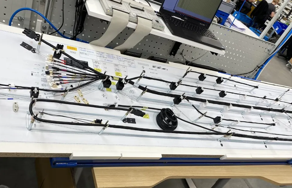
A wire harness, also known as a wiring harness, cable harness, or wiring assembly, is a group of wires, terminals, connectors, and protective components assembled according to a defined electrical schematic and mechanical routing requirement.
Unlike a standard off-the-shelf cable, a custom wire harness is normally designed around the equipment in which it will be installed. Wire lengths, branch positions, connector locations, terminal assignments, and retention points are determined by the application.
A typical wire harness assembly may contain several major groups of components:
- Wires and conductors — Usually stranded copper conductors selected according to current, voltage, flexibility, temperature, and installation requirements.
- Terminals — Electrical contacts crimped or otherwise attached to wire ends. Common contact materials include copper alloys with tin, silver, or gold plating depending on the application.
- Connectors — Connector housings provide mechanical mating, polarization, keying, and electrical interface functions.
- Insulation and protective sleeving — PVC, XLPE, silicone, PTFE, TPE, braided sleeving, heat-shrink tubing, and other materials can provide electrical insulation and environmental protection.
- Retention components — Cable ties, clips, clamps, brackets, and other fixtures maintain the intended routing and prevent excessive movement.
- Identification components — Wire markers, labels, and printed identification support assembly, inspection, maintenance, and traceability.
Terminals and Connectors Must Be Properly Matched
Terminal and connector selection is one of the most important aspects of wire harness design. A connector housing is generally designed for specific terminal families, conductor sizes, insulation diameters, and crimp configurations.
An incorrect combination may result in poor electrical contact, increased contact resistance, insufficient mechanical retention, or terminal back-out during connector mating.
For this reason, engineering documentation should identify the exact wire, terminal, connector housing, cavity position, crimp specification, and applicable inspection requirements.
Wire Harness vs. Cable Assembly
Wire harnesses and cable assemblies are related but are not always interchangeable terms.
A cable assembly typically consists of one or more conductors contained within a cable structure and terminated at one or both ends. A wire harness often contains multiple individual wires arranged into a trunk-and-branch structure, with multiple connectors or termination points.
The distinction is primarily structural and application-specific rather than simply based on the number of wires.
For example:
- A two-ended power cable can be considered a cable assembly.
- A group of power and signal wires branching to several sensors and control boards is more appropriately described as a wire harness.
- An RF coaxial cable terminated with RF connectors is generally treated as a specialized cable assembly.
- A multi-branch assembly connecting a PCB, power supply, sensors, switches, and motors can be designed as a custom wiring harness.
The correct terminology should therefore be defined in the engineering drawing and procurement documentation.
What Are the Common Types of Wire Harnesses?
The structure of a wire harness depends on the electrical architecture, available installation space, service requirements, and mechanical constraints of the final product.
Point-to-Point Wire Harnesses
A point-to-point harness is a relatively simple assembly that connects two primary locations. It is commonly used inside equipment where a direct connection is required between two boards, modules, sensors, or power components.
Its relatively simple structure can make assembly and inspection straightforward.
Branched Wire Harnesses
A branched wire harness contains a main trunk with multiple branches leading to different components.
This configuration is widely used in industrial equipment, control systems, vehicles, and complex electronic products where one harness must distribute power or signals to multiple destinations.
Branch positioning, bend radius, connector orientation, and retention points should be clearly defined during mechanical and electrical design.
Ribbon and Board-Level Harnesses
Ribbon cables, FFCs, and FPCs are frequently used where high connection density and limited routing space are important.
These solutions can provide organized parallel conductors for board-to-board or board-to-module connections. However, their construction and termination methods differ from conventional discrete-wire harnesses.
Modular Wire Harnesses
A modular harness divides a larger wiring system into several independently assembled sections connected through mating interfaces.
This approach can simplify product assembly, maintenance, and replacement of specific sections. The trade-off is additional connectors, mating interfaces, and associated cost.
Modularization is particularly useful when equipment contains replaceable modules or when the manufacturing process needs to be divided into multiple assembly stages.
How Is Wire Gauge Selected?
Wire size is commonly specified using AWG (American Wire Gauge). In the AWG system, a smaller gauge number represents a larger conductor diameter and greater conductor cross-sectional area.
The following table provides representative conductor sizes commonly encountered in electronic and electrical assemblies:
| Wire Gauge | Approx. Conductor Area | Typical Application |
|---|---|---|
| 28 AWG | 0.08 mm² | Low-current signals and internal wiring |
| 26 AWG | 0.13 mm² | Sensor and communication signals |
| 24 AWG | 0.20 mm² | Control and data circuits |
| 22 AWG | 0.33 mm² | General control wiring |
| 20 AWG | 0.52 mm² | Low-power supply circuits |
| 18 AWG | 0.82 mm² | Power leads, fans, and relays |
| 16 AWG | 1.31 mm² | Medium-power circuits |
| 14 AWG | 2.08 mm² | Higher-current branches |
| 12 AWG | 3.31 mm² | Main power and battery connections |
| 10 AWG | 5.26 mm² | High-current power circuits |
These values describe conductor size, but wire gauge alone does not determine allowable current.
Actual ampacity depends on several factors, including:
- Conductor material
- Ambient temperature
- Insulation temperature rating
- Number of conductors in a bundle
- Airflow and heat dissipation
- Installation method
- Continuous versus intermittent current
- Permissible voltage drop
- Required safety margin
Current Capacity and Voltage Drop
For long cable runs, voltage drop can become a significant design consideration. A conductor may theoretically carry the required current while still producing excessive voltage loss at the load.
For power circuits, engineers should therefore evaluate both thermal capacity and electrical performance rather than selecting a conductor based only on nominal current.
For signal circuits, conductor size may be less important than impedance, shielding, crosstalk, capacitance, and electromagnetic compatibility.
How Is Wire Insulation Material Selected?
Wire insulation determines the environmental conditions under which a harness can operate safely and reliably.
Important selection factors include temperature, chemical exposure, flexibility, abrasion resistance, flame behavior, moisture exposure, and cost.
| Insulation Material | Typical Temperature Capability* | Chemical Resistance | Flexibility | Typical Applications |
|---|---|---|---|---|
| PVC | Approx. –20 to 80°C | Moderate | Good | General internal wiring |
| XLPE | Approx. –40 to 125°C | Good | Moderate | Power and industrial applications |
| Silicone | Approx. –60 to 200°C | Moderate | Very good | High-temperature and flexible applications |
| PTFE | Approx. –70 to 260°C | Very good | Moderate | High-temperature and chemically demanding applications |
| TPE | Approx. –40 to 100°C | Good | Very good | Flexible and moving applications |
*Actual ratings depend on the specific wire construction, formulation, standard, and manufacturer specification. Always verify the applicable datasheet.
Temperature Requirements
The selected wire insulation material should be evaluated against the maximum operating temperature rather than simply the normal ambient temperature.
The temperature of the conductor itself can rise because of electrical resistance and current flow. In tightly bundled harnesses, heat dissipation can also be reduced.
Therefore, both ambient temperature and self-heating should be considered during design.
Chemical Resistance
If a harness is exposed to oils, fuels, solvents, cleaning agents, coolants, or other chemicals, chemical compatibility becomes an important selection criterion.
The insulation should be evaluated against the actual chemical environment rather than relying only on general material descriptions.
Flexibility and Repeated Movement
Harnesses installed in moving mechanisms require additional attention to flexibility and bending performance.
Robotic systems, drag chains, automated equipment, and movable assemblies may subject wires to repeated bending. In these applications, conductor construction, strand design, insulation material, bend radius, and routing all contribute to service life.
What Do Different Industries Require?
Although the basic manufacturing process for a wire harness is similar across industries, environmental and reliability requirements can vary substantially.
Industrial Automation
Industrial wire harnesses are commonly used in control cabinets, PLC systems, servo systems, motors, sensors, drives, and machine-control equipment.
Key considerations include:
- Temperature range
- Vibration
- Current capacity
- Electromagnetic compatibility
- Mechanical routing
- Connector retention
- Maintenance requirements
Power and signal wires may need to be physically separated or appropriately shielded to reduce interference.
Communication Equipment
Communication equipment harnesses may be used for power distribution, internal cabinet wiring, data connections, and RF-related applications.
Signal integrity and EMI shielding become increasingly important as operating frequencies and data rates increase.
Depending on the application, engineers may need to evaluate shielding coverage, grounding strategy, connector performance, cable impedance, and routing distance.
New Energy and Energy Storage
Energy storage harnesses and power-related wiring assemblies may connect battery modules, monitoring systems, power conversion equipment, charging systems, and control electronics.
These applications can involve high current and elevated electrical stress. Wire selection, insulation systems, connector ratings, creepage and clearance, mechanical retention, and protection against abrasion must therefore be carefully evaluated.
For high-voltage applications, the applicable electrical safety requirements should be defined at the system level before production.
Security and Monitoring Equipment
Security cameras, access-control systems, intercoms, and monitoring equipment often use compact wire harness assemblies for internal power, signal, and communication connections.
In these applications, compact routing, connector compatibility, production consistency, and cost efficiency can be important design considerations.
Rail Transportation
Railway applications may impose more demanding requirements for flame performance, smoke generation, toxicity, vibration, temperature, and mechanical durability.
For rail transportation wire harnesses, material and component selection should follow the standards applicable to the specific railway application and market.
Medical Electronics
Medical equipment may require highly controlled materials, reliable connections, traceability, and consistent manufacturing processes.
Harnesses used in patient monitoring systems, laboratory equipment, diagnostic instruments, and other medical electronics should be evaluated according to the applicable equipment requirements and regulatory framework.
The harness specification should be developed together with the PCB, enclosure, power system, and mechanical design rather than treated as an isolated component.
What Information Should Be Included in a Wire Harness Drawing?
A professional wire harness drawing should contain sufficient information for repeatable manufacturing and inspection.
Typical documentation includes:
- Wire part number
- Wire gauge and conductor construction
- Wire color
- Wire length
- Insulation type
- Terminal part number
- Connector housing part number
- Cavity or pin assignment
- Crimp specification
- Strip length
- Branch dimensions
- Connector orientation
- Sleeve or tubing requirements
- Labeling requirements
- Test requirements
- Applicable standards
- Revision level
For complex assemblies, a wire list, bill of materials (BOM), connector pinout table, 2D drawing, and 3D routing model can work together to reduce manufacturing ambiguity.
How Is a Wire Harness Built?
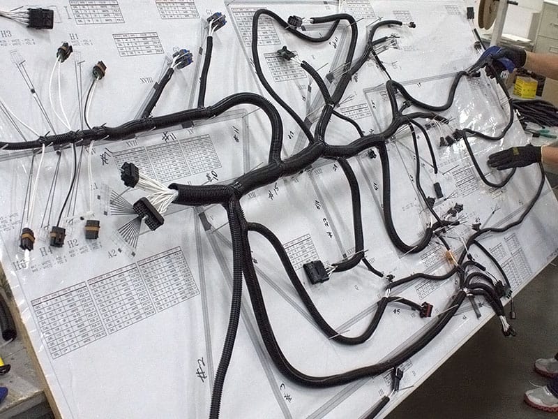
A typical wire harness manufacturing process includes several controlled operations.
1. Wire Cutting
The wire is cut to the specified length according to the manufacturing documentation.
For production assemblies, automated cutting equipment can improve consistency and reduce manual measurement errors.
2. Wire Stripping
The insulation is removed from the specified section of the conductor.
The stripping process must avoid damaging or nicking conductor strands because conductor damage can reduce mechanical and electrical performance.
3. Terminal Crimping
The prepared conductor is inserted into the terminal and compressed using an appropriate crimping tool or applicator.
Crimping is one of the most critical operations in wire harness manufacturing.
Important parameters may include:
- Crimp height
- Crimp width
- Conductor brush
- Insulation support
- Terminal position
- Pull force
- Tooling condition
Crimp quality should be verified using appropriate inspection and testing methods rather than relying solely on visual inspection.
4. Connector Assembly
After terminals are crimped, they are inserted into the correct connector cavities.
The terminal must lock correctly into the housing, and connector keying and polarization must correspond to the intended mating interface.
5. Bundling and Protection
Individual wires are organized into the required routing configuration using tape, braided sleeving, heat-shrink tubing, conduits, clips, or other protective components.
The assembly should maintain the specified bend radius and avoid excessive mechanical stress at connector exits.
6. Identification
Labels and wire markers are applied according to the drawing.
Proper identification improves assembly efficiency, troubleshooting, maintenance, and production traceability.
7. Inspection and Testing
The finished assembly is inspected and electrically tested before shipment.
For applications involving PCB integration, mechanical fit and connector mating should also be verified against the PCB and enclosure.
What Should Be Verified Before Delivery?
A reliable wire harness testing program should be based on the application, drawing, customer requirements, and applicable standards.
IPC/WHMA-A-620 is a widely recognized industry standard covering requirements and acceptance criteria for cable, wire, and harness assemblies. The applicable class and acceptance criteria should be specified according to the product’s intended use.
Common verification activities include:
Continuity Testing
Continuity testing confirms that the intended electrical paths are complete.
It can also be combined with pin-to-pin verification to identify:
- Open circuits
- Short circuits
- Miswires
- Incorrect pin assignments
- Missing connections
Crimp Pull Testing
Crimp pull force testing evaluates the mechanical strength of selected crimp connections.
Sampling frequency and acceptance criteria should be established according to the terminal specification, manufacturing process, customer requirements, and applicable standard.
Insulation Resistance Testing
Insulation resistance testing verifies the electrical isolation between specified conductors or between conductors and shielding/ground where applicable.
Dielectric Withstand Testing
For suitable applications, dielectric withstand testing, commonly known as hipot testing, can verify that the insulation system withstands the specified test voltage without breakdown.
The test voltage and duration must be defined according to the applicable product and safety requirements.
Functional Testing
When the harness is part of a larger electronic assembly, functional verification can confirm that the complete interconnection performs correctly with the intended PCB, power supply, sensors, actuators, or other system components.
How Can Wire Harness Reliability Be Improved?
A reliable wire harness assembly depends on both component selection and process control.
Key practices include:
- Define electrical requirements clearly
Specify voltage, current, signal type, frequency, and allowable voltage drop. - Select the correct wire gauge
Consider current, temperature, bundling, installation method, and voltage drop. - Choose insulation according to the actual environment
Evaluate temperature, chemicals, moisture, abrasion, and flexibility. - Match terminals and connectors correctly
Verify compatibility, crimp requirements, retention, and mating conditions. - Control mechanical routing
Avoid excessive bending, pulling, twisting, and stress concentration around connectors. - Use appropriate protection
Sleeving, tubing, grommets, clips, and shielding should be selected according to the operating environment. - Implement controlled testing
Continuity, pinout, crimp quality, insulation resistance, dielectric withstand, and functional tests should be applied where required. - Maintain documentation and revision control
The drawing, BOM, wire list, connector specification, and test requirements should remain synchronized throughout product development.
How Kingda Supports Electronic Manufacturing Projects
A wire harness is often only one part of a complete electronic product. The harness may connect PCBs, power supplies, displays, sensors, motors, batteries, communication modules, and control systems.
This makes coordination between PCB fabrication, PCB assembly, wiring, mechanical integration, and final testing particularly important.
As an experienced PCB manufacturer and PCB assembly service provider, Kingda provides PCB prototype manufacturing, quick-turn PCB prototyping, and PCB assembly solutions to support customers from initial design validation through full-scale production.
Kingda’s capabilities can support projects through several stages:
PCB Prototype Manufacturing
During early development, PCB prototypes allow engineers to validate circuit functionality, component selection, interfaces, and mechanical integration before committing to larger production volumes.
Quick-Turn PCB Prototyping
For development projects where design iterations are frequent, quick-turn PCB prototyping helps shorten the path from design verification to physical testing.
PCB Assembly
Kingda provides PCB assembly solutions to integrate electronic components onto fabricated circuit boards, supporting both prototype development and production-oriented requirements.
DFM-Oriented Engineering Support
Design-for-manufacturing considerations can be incorporated before production to identify potential manufacturing issues and improve the transition from prototype to repeatable production.
Prototype-to-Production Support
By combining PCB manufacturing and PCB assembly, Kingda can support customers as designs progress from initial verification toward small-batch and production manufacturing.
For products that include wiring harnesses, the PCB, connector interfaces, cable routing, enclosure dimensions, and system-level testing should be considered together. This approach helps reduce integration problems between separately developed electronic and mechanical assemblies.
Frequently Asked Questions
Q1: What is the difference between a wire harness and a cable assembly?
A wire harness generally organizes multiple individual wires into a defined structure, often including multiple branches and termination points. A cable assembly may use one or more conductors within a cable structure and typically connects defined endpoints.
The exact terminology depends on the construction and application.
Q2: Does a higher AWG number mean a thicker wire?
No. AWG is an inverse sizing system. A higher AWG number represents a smaller conductor.
For example, 28 AWG is substantially smaller than 12 AWG.
Q3: Can different wire gauges be used in one harness?
Yes. A single wire harness can contain different wire gauges when different circuits have different current, voltage, signal, or mechanical requirements.
Each wire must be matched with the appropriate terminal and connector system.
Q4: How is the insulation temperature rating selected?
The insulation should be selected based on the maximum expected operating temperature, conductor self-heating, environmental conditions, and the applicable wire specification.
The actual temperature rating should always be confirmed using the manufacturer’s datasheet.
Q5: Is crimping or soldering better for wire harnesses?
Crimping is widely used for production wire harnesses because it can provide a repeatable mechanical and electrical connection when the terminal, wire, tooling, and process are properly matched.
Soldering can also be appropriate for specific applications and terminal designs. The correct method depends on the component and applicable manufacturing requirements.
Q6: What testing does a wire harness require?
Typical wire harness testing can include continuity and pinout testing, crimp pull-force verification, insulation resistance testing, dielectric withstand testing, and functional testing where applicable.
The required tests should be defined by the product specification and applicable standards.
Q7: What determines wire harness cost?
The cost of a custom wire harness is influenced by:
- Wire type and length
- Wire gauge
- Number and type of terminals
- Connector selection
- Number of branches
- Sleeving and protection
- Labeling requirements
- Crimping and assembly operations
- Testing requirements
- Production volume
Connectors and specialized terminals can represent a significant portion of the total assembly cost.
Q8: When should a modular harness be used?
A modular wire harness can be useful when a product contains replaceable modules, requires service access, or needs to divide assembly into multiple production stages.
However, additional connectors increase the number of interfaces and may increase material and assembly costs. The decision should therefore be based on the product architecture and service strategy.
Conclusion
A well-designed wire harness is more than a collection of wires and connectors. It is an engineered interconnection system that must satisfy electrical, mechanical, thermal, environmental, manufacturing, and service requirements.
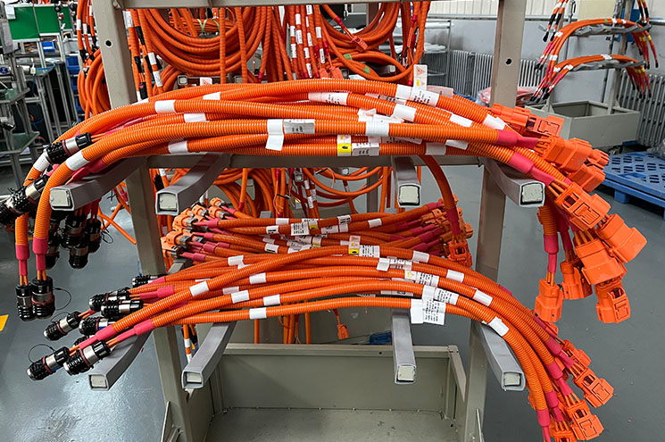
Successful wire harness manufacturing starts with accurate documentation and component selection, followed by controlled cutting, stripping, crimping, connector insertion, bundling, labeling, inspection, and testing.
For electronic products that combine wiring with printed circuit boards, system-level coordination is equally important. Kingda supports customers with PCB prototype manufacturing, quick-turn PCB prototyping, and PCB assembly solutions, helping move electronic products from initial design validation toward reliable production.
By considering the PCB, PCBA, connectors, wiring harness, mechanical structure, and testing requirements as part of one engineering process, manufacturers can improve production consistency, simplify integration, and build more reliable electronic products.