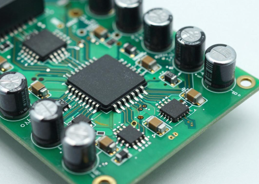
HVAC Circuit Board: PCB Design, PCB Manufacturing, Components & Applications
Have you ever wondered how your air conditioner, heating system, or ventilation equipment operates quietly in the background while maintaining a comfortable indoor environment?
Modern heating, ventilation, and air conditioning (HVAC) systems rely heavily on electronic control technology. At the center of many of these systems is an HVAC Circuit Board, also known as an HVAC control board. This electronic assembly coordinates sensors, motors, compressors, valves, thermostats, communication interfaces, and safety circuits to ensure that the HVAC system operates according to its programmed requirements.
An HVAC control board can continuously collect information from temperature and pressure sensors, process this information through a microcontroller, and then control system components based on operating conditions. This allows modern HVAC equipment to provide more precise temperature control, improved energy efficiency, diagnostics, and integration with smart-home or building-management systems.
This article explains what an HVAC circuit board is, why it is important, how to approach PCB Design for HVAC applications, the major components used on these boards, the manufacturing process, and where HVAC control boards are used in real-world systems.
What Is an HVAC Circuit Board?
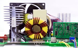
An HVAC Circuit Board is an electronic control assembly designed to monitor and control the operation of heating, ventilation, and air-conditioning equipment.
It functions as the electronic control center of an HVAC system. Depending on the system architecture, the board can receive inputs from thermostats and sensors, process these signals using a microcontroller or other control circuitry, and generate outputs that operate components such as:
- Compressors
- Blower motors
- Fans
- Heating elements
- Gas valves
- Electronic expansion valves
- Dampers
- Relays and contactors
- Pumps
- Safety devices
A typical HVAC control board may also include power-conversion circuitry, protection devices, communication interfaces, memory, status indicators, and diagnostic functions.
The exact architecture varies considerably between residential air conditioners, heat pumps, furnaces, commercial HVAC systems, and automotive climate-control systems.
Why Is an HVAC Circuit Board Important?
The HVAC circuit board is important because it coordinates multiple subsystems that must operate together safely and efficiently.
System Coordination
The control board receives information from thermostats and sensors and determines when heating, cooling, ventilation, or other functions should be activated.
For example, when the measured temperature differs from the desired setpoint, the controller can initiate an appropriate sequence of operations rather than simply switching one component on or off.
Energy Management
Modern HVAC systems need to balance comfort and energy consumption.
A controller can regulate operating cycles, fan speeds, compressor operation, and other functions according to system demand. Variable-speed systems may use more sophisticated control algorithms to continuously adjust operating conditions.
Safety
HVAC equipment can contain high-voltage circuits, hot surfaces, rotating machinery, pressurized refrigerant systems, or combustion processes.
The control board can monitor safety-related inputs and initiate protective actions when abnormal conditions are detected.
Diagnostics
Many HVAC control boards provide diagnostic information through LEDs, displays, communication interfaces, or stored fault codes.
This can help technicians identify problems involving sensors, motors, communication, power supplies, or other subsystems.
Smart Connectivity
Modern HVAC systems can communicate with smart thermostats, building-management systems, mobile applications, and other equipment.
Depending on the system, communication can use wired or wireless interfaces such as RS-485-based protocols, Ethernet, Wi-Fi, Bluetooth, or proprietary communication buses.
HVAC Circuit Board Design Basics
Effective PCB Design begins with understanding the complete HVAC system rather than designing the circuit board in isolation.
1. Define System Requirements
Before creating the schematic, engineers should establish the system’s electrical, mechanical, environmental, and functional requirements.
Important parameters include:
- Input voltage
- Operating current
- Maximum load
- Switching requirements
- Operating temperature
- Humidity
- Vibration
- Sensor types
- Communication interfaces
- Required protection
- Mechanical dimensions
- Expected service life
The designer should also determine which circuits are safety-critical and which sections involve hazardous voltages or high-energy loads.
2. Develop the Schematic
The schematic should clearly define the major functional blocks, including:
- AC/DC or DC/DC power supply
- Microcontroller
- Sensor interfaces
- Relay or switching circuits
- Motor-control circuits
- Communication interfaces
- Protection circuits
- Memory
- User-interface connections
- Diagnostic indicators
Separating these functional blocks makes it easier to analyze power distribution, signal paths, isolation, and troubleshooting requirements.
3. Select Appropriate Components
Component selection should be based on electrical ratings, environmental conditions, reliability, availability, and lifecycle requirements.
Typical components include microcontrollers, thermistors, temperature sensors, pressure sensors, capacitors, resistors, transformers, relays, MOSFETs, power semiconductors, connectors, fuses, and communication ICs.
For HVAC applications, component temperature ratings and switching endurance can be particularly important because control boards may operate for long periods under changing environmental conditions.
4. PCB Layout
The PCB layout should separate high-voltage and low-voltage circuits appropriately and provide sufficient creepage and clearance according to the applicable safety requirements.
Important layout considerations include:
- High-voltage isolation
- Grounding
- Return-current paths
- EMI/EMC control
- Thermal management
- Power-plane design
- Sensitive analog signal routing
- Switching-node control
- Connector placement
- Mechanical mounting
The layout should also consider the actual enclosure and airflow conditions rather than assuming an ideal laboratory environment.
5. Simulation and Verification
Simulation can help engineers evaluate important sections of the circuit before manufacturing a physical prototype.
Power supplies, switching circuits, motor-control interfaces, sensor inputs, and communication interfaces may require particular attention.
However, simulation should complement rather than replace physical testing.
6. Embedded Firmware and Control Algorithms
An HVAC control board often requires embedded firmware to interpret sensor data and control system behavior.
Firmware may implement:
- Temperature control
- Fan-speed control
- Compressor sequencing
- Defrost control
- Fault detection
- Sensor diagnostics
- Safety shutdown
- Timing functions
- Communication protocols
- Energy-management algorithms
The hardware and firmware should therefore be developed together because software requirements can influence the PCB’s processor, memory, interfaces, and sensing circuitry.
7. Prototype Manufacturing and Testing
After the design has been reviewed, prototype boards can be fabricated and assembled.
Testing may include:
- Sensor accuracy
- Power-supply stability
- Relay operation
- Motor-control performance
- Communication response
- Thermal performance
- EMC behavior
- Safety-related functions
Test results can then be used to refine the hardware and firmware before mass production.
Main Functions of an HVAC Circuit Board
An HVAC control board performs several interconnected functions.
1. System Coordination
The controller receives information from thermostats and sensors and coordinates the operation of different HVAC components.
For example, cooling operation may require a particular sequence involving the compressor, indoor fan, outdoor fan, valves, and safety monitoring.
2. Power Management
The control board distributes or converts electrical power for different circuits.
Low-voltage control electronics may require a regulated DC supply, while high-power loads may be controlled through relays, contactors, triacs, MOSFETs, or other switching devices.
3. Temperature Control
Temperature sensors provide feedback to the controller.
The controller compares measured conditions with target values and adjusts system operation accordingly.
Depending on the HVAC system, control may range from simple hysteresis-based on/off control to more sophisticated variable-speed or feedback-control algorithms.
4. Safety Monitoring
HVAC systems may use multiple sensors and protection devices.
Examples include:
- Flame sensors
- Pressure switches
- Temperature sensors
- Overcurrent protection
- Motor protection
- Refrigerant-related sensors
- Limit switches
When an unsafe condition is detected, the control system can disable relevant functions or place the equipment into a safe state.
5. Communication
The control board may exchange information with thermostats, displays, remote controllers, outdoor units, indoor units, or building-management systems.
Communication interfaces depend on the equipment architecture and may include wired or wireless technologies.
6. Diagnostic Management
The controller can monitor abnormal operating conditions and record or report fault information.
LED indicators, error codes, communication messages, and nonvolatile memory can all support maintenance and troubleshooting.
Key HVAC Circuit Board Components
The exact component list varies according to the HVAC system, but several components appear frequently.
| Component | Primary Function |
|---|---|
| Microcontroller Unit (MCU) | Processes sensor inputs, executes control algorithms, and manages system outputs |
| Temperature Sensors / Thermistors | Measure air, coil, pipe, or component temperature |
| Pressure Sensors / Switches | Monitor system pressure and support protection functions |
| Resistors | Provide current limiting, voltage division, biasing, sensing, and signal conditioning |
| Capacitors | Provide filtering, decoupling, energy storage, and noise suppression |
| Power Transformer | Provides electrical isolation and/or voltage conversion in applicable architectures |
| Power Supply ICs | Generate regulated DC voltages for control electronics |
| Relays and Contactors | Switch higher-power loads such as compressors, fans, and heaters |
| MOSFETs / Power Semiconductors | Provide electronic switching and power control |
| Fuses | Protect circuits against excessive current |
| Connectors and Terminals | Interface the PCB with sensors, motors, power wiring, and other system modules |
| LED Indicators | Display operating status or diagnostic information |
| Communication Modules | Provide wired or wireless connectivity |
| EEPROM / Flash Memory | Store firmware, configuration data, calibration information, or fault records |
Microcontroller Unit
The MCU acts as the processing center of the control board. It receives sensor information, executes firmware, and controls outputs.
The processor should be selected according to the required processing speed, ADC resolution, communication interfaces, memory, temperature range, and lifecycle requirements.
Temperature Sensors
NTC thermistors are common because of their simplicity and low cost. Other systems may use integrated temperature sensors or RTDs where their characteristics better match the measurement requirements.
Sensor placement is just as important as sensor selection because incorrect thermal coupling can produce inaccurate measurements.
Relays and Switching Devices
HVAC systems frequently need to control loads that require considerably more power than a microcontroller can provide.
Relays, contactors, triacs, MOSFETs, IGBTs, and other power devices can therefore be used as interfaces between the low-power control circuitry and higher-power equipment.
Capacitors and Resistors
Passive components perform fundamental functions throughout the control board.
Resistors can provide sensing and signal-conditioning functions, while capacitors can stabilize power rails, filter noise, suppress transients, and support switching circuits.
Power Supply and Transformer
The control board requires a stable power source for its electronics.
Depending on the architecture, the power supply can include a transformer, rectifier, switching regulator, linear regulator, isolation circuitry, filtering, and surge protection.
Protection Components
Protection components can include:
- Fuses
- TVS diodes
- Varistors
- Current-sensing circuits
- Thermal protection devices
- Overvoltage protection
- Reverse-polarity protection
Their purpose is to reduce the likelihood that electrical transients or abnormal operating conditions will damage critical circuitry.
Connectors and Terminals
Connectors provide interfaces between the PCB and the rest of the HVAC system.
They must be selected according to current, voltage, temperature, mechanical stress, environmental exposure, and required service life.
Communication Interfaces
Depending on the product, the board may support wired communication, wireless connectivity, or proprietary system buses.
Communication design should consider electromagnetic interference, isolation, connector configuration, and protocol requirements.
Nonvolatile Memory
EEPROM or flash memory can store firmware, calibration constants, configuration parameters, operating information, and fault records.
HVAC PCB Manufacturing Process
Reliable PCB Manufacturing is essential because HVAC control boards may operate continuously while being exposed to temperature changes, vibration, humidity, electrical transients, and switching noise.
A typical manufacturing workflow includes the following stages.
1. PCB Fabrication
The PCB manufacturer converts the finalized design data into physical circuit boards through processes such as imaging, etching or additive circuit formation, drilling, copper plating, lamination, solder-mask application, and surface finishing.
2. PCB Assembly
Electronic components are installed using surface-mount technology (SMT), through-hole technology (THT), or a combination of both.
Large connectors, relays, transformers, and other mechanical components may require through-hole assembly because of their mechanical and electrical requirements.
3. Reflow and Soldering
SMT components are typically soldered using a controlled reflow process. Through-hole components may be soldered using wave soldering, selective soldering, or manual processes depending on the design.
4. Inspection
Inspection can include:
- Automated optical inspection (AOI)
- X-ray inspection
- Visual inspection
- Solder-joint inspection
- Dimensional inspection
The inspection strategy should be based on the board’s complexity and reliability requirements.
5. Electrical Testing
Electrical tests can verify:
- Continuity
- Isolation
- Power-rail performance
- Component behavior
- Communication interfaces
- Input/output functions
Functional testing is particularly valuable for control boards because it can verify whether the complete assembly behaves as expected.
6. Environmental and Reliability Testing
Depending on the intended application, testing may include:
- Temperature cycling
- High-temperature operation
- Humidity testing
- Vibration testing
- Electrical surge testing
- Long-duration operation
- Connector cycling
The test plan should reflect the actual HVAC operating environment.
Applications of HVAC Circuit Boards
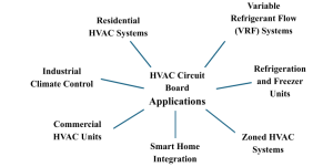
HVAC circuit boards are used in a wide range of heating, cooling, and ventilation equipment.
Residential Air Conditioning
Residential air conditioners use control boards to coordinate compressors, indoor and outdoor fans, sensors, thermostats, and safety functions.
Modern variable-speed systems may require more sophisticated control electronics than basic fixed-speed systems.
Heat Pumps
Heat pumps use control electronics to coordinate heating and cooling modes.
The controller may manage compressors, fans, valves, temperature sensors, defrost functions, and communication between indoor and outdoor units.
Furnaces and Heating Systems
Heating systems use control boards to coordinate ignition, flame monitoring, blowers, temperature sensing, and safety devices.
In combustion-based equipment, safety monitoring is particularly important.
Commercial HVAC Systems
Commercial buildings often use more complex HVAC control architectures.
Circuit boards may interface with:
- Variable-frequency drives
- Building-management systems
- Multiple sensors
- Dampers
- Pumps
- Fans
- Compressors
- Heating and cooling zones
Industrial HVAC
Industrial environments may impose more demanding temperature, vibration, contamination, and operating-cycle requirements.
Industrial HVAC control boards therefore often require careful selection of components and protective measures.
Smart HVAC Systems
Connected HVAC equipment can communicate with smart thermostats, mobile applications, cloud services, and building-management systems.
The control board becomes an important interface between physical HVAC equipment and digital control infrastructure.
Automotive Climate-Control Systems
Automotive heating and air-conditioning systems also rely on electronic control boards and modules to manage blower motors, temperature sensors, actuators, compressors, valves, and user controls.
Automotive applications require additional consideration of vibration, temperature cycling, electrical transients, and vehicle-specific qualification requirements.
Important HVAC PCB Design Challenges
High-Voltage and Low-Voltage Separation
HVAC control boards may contain both low-voltage control circuitry and high-voltage power circuits.
PCB layout must provide appropriate creepage, clearance, insulation, and isolation according to the applicable safety requirements.
EMI and EMC
Relays, motors, compressors, switching power supplies, and power semiconductors can generate electromagnetic noise.
Designers should therefore carefully control:
- Switching loops
- Ground return paths
- Power routing
- Filtering
- Signal routing
- Shielding
- Component placement
Thermal Management
Power components generate heat during operation.
The PCB design may need to use:
- Large copper areas
- Thermal vias
- Heat sinks
- Appropriate component spacing
- Forced airflow
- Thermally conductive interfaces
Thermal simulation and measurement can help verify the design.
Environmental Reliability
HVAC equipment may operate in environments with significant temperature and humidity variations.
The PCB material, components, connectors, solder joints, coatings, and enclosure should be evaluated against the actual environment.
Long Product Lifecycles
HVAC products may remain in the market for many years. Component obsolescence can therefore become a significant engineering and manufacturing issue.
Designers should consider:
- Component availability
- Second-source options
- Lifecycle status
- Qualification requirements
- Change-control procedures
Serviceability
Because HVAC equipment requires field maintenance, the control board should ideally provide useful diagnostic information and practical access to connectors, test points, fuses, and service interfaces.
How to Improve HVAC Circuit Board Reliability
Several design and manufacturing practices can improve the reliability of HVAC control boards.
Use Appropriate Component Ratings
Components should have sufficient voltage, current, temperature, and endurance margins for their intended operating conditions.
Control Electrical Transients
Motors, relays, compressors, and inductive loads can generate transient voltages. Appropriate suppression and filtering should be incorporated into the circuit design.
Optimize PCB Layout
High-current and high-noise circuits should be separated from sensitive sensor and communication circuits where appropriate.
Perform DFM Reviews
A design-for-manufacturing review can identify issues involving trace widths, spacing, component placement, soldering, test access, and assembly yield before production begins.
Validate Under Real Conditions
Testing should replicate realistic temperature, humidity, vibration, electrical loading, and operating-cycle conditions whenever practical.
Maintain Manufacturing Traceability
Production records and component traceability can make it easier to identify the source of quality problems and manage engineering changes.
How to Choose an HVAC PCB Manufacturer
When selecting a supplier for HVAC control boards, engineers should evaluate both PCB fabrication and assembly capabilities.
Technical Capability
Check whether the manufacturer can support:
- Multilayer PCB
- High-current PCB
- Controlled impedance where required
- SMT and THT assembly
- Heavy copper where needed
- Thermal-management structures
- High-voltage PCB layout requirements
- Fine-pitch components
Quality Control
Review the supplier’s inspection and testing capabilities, including AOI, X-ray inspection, electrical testing, and functional testing.
Component Supply
Because HVAC products can have long lifecycles, component sourcing and lifecycle management should be considered from the beginning of the project.
Engineering Support
A capable manufacturer should be able to provide DFM feedback and identify potential manufacturing problems before production.
Environmental and Reliability Testing
For demanding applications, determine whether the supplier can support or coordinate appropriate reliability testing based on the product requirements.
Cost and Production Volume
PCB cost depends on board size, layer count, copper thickness, materials, components, assembly complexity, testing, and production volume.
The appropriate supplier should therefore be evaluated using total manufacturing requirements rather than PCB unit price alone.
Kingda HVAC PCB Manufacturing Support
Kingda can support HVAC electronics projects with PCB fabrication and assembly solutions tailored to the requirements of heating, ventilation, air-conditioning, and climate-control equipment.
Depending on the project, the manufacturing process can address multilayer PCB construction, power circuitry, SMT and through-hole assembly, thermal-management requirements, component placement, inspection, electrical testing, and DFM optimization.
For HVAC applications, engineers should provide key information such as operating voltage, current, environmental conditions, load types, safety requirements, communication interfaces, expected service life, and production volume. This allows the PCB design and manufacturing process to be aligned with the actual application.
Conclusion
An HVAC Circuit Board is much more than a simple electronic control board. It acts as the coordination center connecting sensors, processors, power circuits, motors, compressors, valves, communication interfaces, and safety systems.
A successful PCB Design for HVAC equipment must consider electrical safety, thermal management, EMI/EMC, environmental conditions, component reliability, serviceability, and long-term availability.
At the same time, dependable PCB Manufacturing requires controlled fabrication, consistent assembly, inspection, electrical testing, and appropriate reliability validation.
As HVAC systems become more energy-efficient, connected, automated, and intelligent, their control electronics will continue to become more sophisticated. A well-engineered HVAC PCB can help equipment achieve accurate control, efficient operation, reliable diagnostics, and long-term system performance.