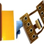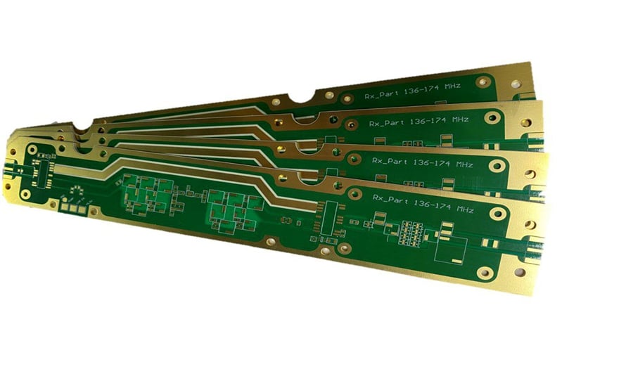
Rogers 4350B PCB: PCB Design, PCB Manufacturing, Properties, Benefits & Applications
As electronic systems continue to operate at higher frequencies and data rates, choosing the right substrate material has become increasingly important. Conventional FR-4 materials can be suitable for many low- and medium-frequency applications, but their electrical characteristics may become more challenging to control as operating frequency increases.
This is where high-performance RF and microwave laminates become valuable.
At frequencies ranging from the megahertz to the gigahertz range, even small variations in dielectric properties can affect impedance, propagation delay, insertion loss, and overall signal integrity. Rogers 4350B PCB technology addresses these challenges by providing stable electrical properties, low dielectric loss, good thermal performance, and compatibility with conventional PCB fabrication processes.
Rogers 4350B is widely considered for RF, microwave, high-frequency, automotive radar, telecommunications, aerospace, and other demanding electronic applications.
This guide explains what Rogers 4350B is, its key properties, advantages, applications, manufacturing considerations, and how it compares with conventional FR-4 materials.
What Is Rogers 4350B?
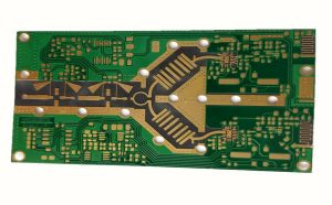
Rogers RO4350B is a high-frequency circuit material manufactured by Rogers Corporation. It is a ceramic-filled hydrocarbon thermoset laminate designed for RF and microwave applications.
Unlike conventional FR-4, which is primarily optimized for general-purpose electronic applications, RO4350B is engineered to provide more predictable electrical performance at high frequencies.
Its combination of controlled dielectric properties, low dissipation factor, thermal stability, dimensional stability, and relatively conventional processing characteristics makes it suitable for demanding PCB Design applications.
Rogers 4350B is especially useful when engineers need to maintain controlled impedance and minimize dielectric losses while still using manufacturing processes that are relatively compatible with standard PCB fabrication.
Why Is Rogers 4350B Important for High-Frequency PCB Design?
When signal frequency increases, the PCB substrate becomes an active part of the transmission system rather than simply a mechanical support structure.
The dielectric constant, dissipation factor, copper roughness, dielectric thickness, trace geometry, and layer stack-up all influence signal behavior.
For this reason, high-frequency PCB Design requires much tighter control over material characteristics than many conventional digital designs.
Rogers 4350B provides a controlled dielectric environment that can help engineers:
- Maintain predictable impedance
- Reduce dielectric signal loss
- Control propagation delay
- Improve signal integrity
- Support high-frequency transmission lines
- Reduce performance variation over temperature
- Build RF and microwave circuits with repeatable electrical characteristics
These characteristics make RO4350B a practical substrate option for applications where conventional FR-4 may not provide the required high-frequency performance.
Key Properties of Rogers 4350B
The electrical and thermal characteristics of Rogers 4350B are among its most important advantages.
1. Controlled Dielectric Constant (Dk)
Rogers 4350B is commonly specified with a Dk around 3.48 at 10 GHz under the manufacturer’s stated test conditions.
A stable dielectric constant helps engineers accurately calculate transmission-line dimensions and impedance.
However, designers should not treat Dk as a single universal number. The reported Dk can vary depending on the test method, frequency, resin content, laminate construction, and material thickness.
Therefore, the manufacturer’s datasheet and the specific laminate construction should be used when performing precision RF PCB Design.
2. Low Dissipation Factor (Df)
RO4350B has a typical dissipation factor of approximately 0.0037 at 10 GHz.
A low Df means that less electromagnetic energy is dissipated within the dielectric material.
This is particularly important for:
- RF transmission lines
- Microwave circuits
- Antenna systems
- Filters
- Power amplifiers
- Low-noise amplifiers
- High-frequency communication systems
Lower dielectric loss can help improve insertion loss and overall system efficiency.
3. Temperature Coefficient of Dk
The temperature coefficient of dielectric constant, or TCDk, indicates how much the dielectric constant changes as temperature changes.
Rogers 4350B is designed to provide relatively stable dielectric performance over temperature, which can help reduce frequency-dependent electrical variation in environments with changing operating temperatures.
For high-reliability designs, engineers should evaluate the complete thermal behavior of the laminate rather than considering TCDk alone.
4. High Glass Transition Temperature
Rogers 4350B has a glass transition temperature (Tg) above 280°C.
A high Tg provides good resistance to thermal softening and helps the material withstand the elevated temperatures associated with PCB assembly processes.
It is important to distinguish Tg from the maximum continuous operating temperature. Actual operating limits should always be determined from the manufacturer’s specifications and the requirements of the finished PCB.
5. Low Moisture Absorption
High-frequency PCB materials can be sensitive to moisture because water can alter dielectric behavior and increase losses.
RO4350B has relatively low moisture absorption compared with many conventional PCB materials, helping maintain electrical consistency in demanding environments.
6. Thermal Performance
RO4350B provides useful thermal characteristics for RF and microwave applications.
Thermal performance becomes increasingly important when circuits contain power amplifiers, RF transistors, or other components that generate significant heat.
The overall thermal performance of the finished PCB still depends on copper thickness, copper distribution, vias, heatsinks, dielectric construction, component placement, and the system’s cooling method.
Main Applications of Rogers 4350B PCB
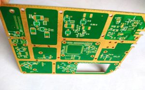
The electrical and thermal characteristics of Rogers 4350B make it suitable for a broad range of high-frequency applications.
1. Telecommunications and Networking
Modern telecommunications systems require high-speed and high-frequency signal transmission.
Rogers 4350B can be used in:
- Base-station RF circuits
- Antenna systems
- RF power amplifiers
- Filters
- Signal distribution networks
- Microwave communication equipment
- Satellite communication systems
Its low dielectric loss and controlled Dk can help engineers maintain predictable RF performance.
For 5G and other advanced wireless systems, material selection becomes especially important as operating frequencies increase.
2. Aerospace and Defense Electronics
Aerospace and defense systems often require stable electrical performance across challenging temperature and environmental conditions.
Rogers 4350B can be considered for:
- Radar systems
- Antenna arrays
- RF front-end modules
- Navigation equipment
- Microwave communication systems
- Electronic warfare-related RF equipment
- Satellite electronics
Low-loss dielectric materials can be valuable in systems where signal attenuation and phase stability are critical design considerations.
3. Automotive Radar and ADAS
Automotive radar systems increasingly operate at high frequencies, including the widely used 76–81 GHz automotive radar band.
For these applications, the PCB substrate can have a significant influence on transmission-line loss, impedance, phase behavior, and antenna performance.
Rogers 4350B and related high-frequency materials can therefore be considered for radar modules and RF structures used in:
- Adaptive cruise control
- Collision detection
- Blind-spot monitoring
- Parking assistance
- Object detection
- Advanced Driver Assistance Systems (ADAS)
For millimeter-wave applications, however, engineers must verify whether the selected laminate grade and construction are appropriate for the exact operating frequency.
4. Microwave and Millimeter-Wave Electronics
Microwave and millimeter-wave systems place particularly demanding requirements on PCB materials.
The millimeter-wave spectrum is generally considered to cover approximately 30 GHz to 300 GHz.
At these frequencies, conductor loss, dielectric loss, surface roughness, layer-to-layer registration, impedance tolerance, and material variation can significantly influence performance.
Rogers 4350B can be used in selected high-frequency designs, but the specific laminate construction must be evaluated against the target frequency and electrical requirements.
5. RF Power Amplifiers and Low-Noise Amplifiers
Power amplifiers require efficient signal transmission and effective thermal management, while low-noise amplifiers require careful control of loss and unwanted parasitic effects.
Rogers 4350B can provide a suitable substrate for RF amplifier circuits where low dielectric loss and stable electrical performance are important.
These circuits are commonly found in wireless communication equipment, satellite systems, radar equipment, and RF front-end modules.
6. High-Speed Digital Circuits
Although Rogers 4350B was developed primarily for RF and microwave applications, high-performance laminate technology can also be considered for certain high-speed digital designs.
As data rates increase, transmission lines behave increasingly like controlled-impedance structures.
In such designs, stable Dk and low dielectric loss can help engineers manage:
- Signal attenuation
- Propagation delay
- Impedance
- Crosstalk
- Eye-diagram performance
- High-speed clock integrity
The choice between FR-4 and a high-frequency laminate should be based on actual system requirements rather than frequency alone.
Benefits of Using Rogers 4350B
1. Better High-Frequency Electrical Performance
One of the main benefits of Rogers 4350B is its controlled electrical performance.
Compared with many conventional FR-4 materials, RO4350B offers lower dielectric loss and more predictable high-frequency characteristics.
This can help engineers design RF and microwave transmission lines with lower insertion loss and better signal integrity.
2. Lower Dielectric Loss
A low dissipation factor is especially valuable when signals travel over relatively long electrical paths or when circuits operate at high frequencies.
Lower dielectric loss can improve energy efficiency and help maintain signal amplitude.
This is important in antennas, filters, amplifiers, communication modules, and microwave circuits.
3. Stable Electrical Performance Over Temperature
Temperature changes can affect the dielectric properties of PCB materials.
Rogers 4350B is designed to provide relatively stable dielectric performance, helping reduce electrical drift in applications exposed to changing operating temperatures.
This can be valuable in automotive, aerospace, outdoor telecommunications, and industrial systems.
4. Good Thermal Performance
High-frequency power circuits can generate significant heat.
Rogers 4350B offers useful thermal performance, while its relatively high Tg also provides good resistance to thermal effects during PCB assembly.
Nevertheless, thermal management must be designed at the system level. A high-performance laminate alone cannot replace appropriate copper planes, thermal vias, heatsinks, or cooling structures.
5. Conventional PCB Processing Compatibility
One important advantage of RO4350B is that it can be processed using many conventional PCB manufacturing techniques.
This can simplify fabrication compared with some PTFE-based high-frequency materials, although manufacturers still need to follow the material supplier’s recommended processing conditions.
Depending on the design, standard processes such as drilling, imaging, etching, plating, lamination, and surface finishing can be incorporated into the overall PCB Manufacturing workflow.
6. Suitable for Hybrid Multilayer Designs
Some advanced electronic products combine high-frequency RF circuits with conventional digital and power circuits.
In these cases, hybrid multilayer structures may combine different dielectric materials within the same PCB architecture.
Rogers 4350B can be considered for such designs when the material stack-up, bonding system, CTE behavior, processing compatibility, and electrical requirements have been properly evaluated.
Rogers 4350B vs. FR-4
FR-4 remains one of the most widely used PCB materials because of its cost-effectiveness, mechanical performance, and broad manufacturing compatibility.
However, FR-4 is not necessarily optimized for demanding RF and microwave applications.
| Property | Rogers 4350B | Typical FR-4 |
|---|---|---|
| Primary application | RF, microwave, high-frequency | General-purpose electronics |
| Dk | Approximately 3.48 at 10 GHz under specified test conditions | Varies significantly by material and frequency |
| Df | Approximately 0.0037 at 10 GHz | Generally higher and more frequency-dependent |
| High-frequency loss | Low | Higher |
| Thermal performance | Designed for demanding applications | Depends on grade |
| Tg | >280°C | Typically lower, depending on grade |
| Cost | Higher | Lower |
| RF/microwave suitability | Excellent for appropriate designs | Limited for demanding applications |
| Processing | Compatible with many conventional PCB processes | Widely established |
The comparison does not mean that Rogers 4350B should replace FR-4 in every design.
For cost-sensitive, low- to moderate-frequency electronics, FR-4 may remain entirely appropriate.
For demanding RF and microwave systems, a low-loss laminate such as RO4350B may provide electrical characteristics that are difficult to achieve with standard FR-4.
Rogers 4350B PCB Manufacturing Considerations
Although Rogers 4350B is compatible with many conventional fabrication processes, high-frequency PCB manufacturing requires tighter process control than standard PCB production.
Material Selection
The exact laminate thickness and copper foil construction must be selected according to:
- Operating frequency
- Required impedance
- Trace width
- Dielectric thickness
- Power level
- Thermal requirements
- Mechanical requirements
- Layer count
Controlled Impedance
Controlled impedance is one of the most important requirements in RF and microwave PCB manufacturing.
Trace width, copper thickness, dielectric thickness, Dk, solder mask, and stack-up all influence impedance.
Manufacturers should therefore verify impedance calculations and fabrication tolerances before production.
Copper Surface Roughness
At high frequencies, current tends to concentrate near the conductor surface due to the skin effect.
As a result, copper surface roughness can contribute to additional conductor loss.
For demanding RF applications, copper foil type and surface roughness should be considered during material and stack-up selection.
Drilling and Plating
High-frequency PCB manufacturing still requires reliable holes, vias, and plated interconnections.
Drilling quality, hole-wall condition, copper plating thickness, and registration accuracy can influence both electrical and mechanical performance.
Lamination and Dimensional Stability
Multilayer RF boards require controlled lamination processes to maintain consistent dielectric thickness and layer alignment.
Even small dimensional variations can affect impedance and phase performance at high frequencies.
Surface Finish
The surface finish should be selected based on solderability, component pitch, RF requirements, environmental conditions, and assembly process.
ENIG, ENEPIG, immersion silver, immersion tin, and other finishes may be considered depending on the application.
PCB Design Guidelines for Rogers 4350B
Effective PCB Design requires the material properties to be incorporated into the design from the beginning.
1. Define the Operating Frequency
The target frequency determines the importance of Dk, Df, copper roughness, dielectric thickness, and transmission-line geometry.
A laminate that performs well at a few gigahertz may not automatically provide the same performance at tens of gigahertz.
2. Use the Correct Material Data
Do not rely on a generic Dk value when designing a precision RF circuit.
Use the material manufacturer’s data corresponding to the actual laminate construction and applicable test method.
3. Control Impedance
RF transmission lines should be designed around the required characteristic impedance.
Engineers should coordinate with the PCB manufacturer to ensure the fabricated dielectric thickness, copper thickness, and trace dimensions remain within the required tolerances.
4. Minimize Unnecessary Discontinuities
Connectors, vias, pads, bends, transitions, and layer changes can introduce impedance discontinuities.
High-frequency layouts should minimize unnecessary transitions and use carefully engineered RF structures.
5. Maintain a Proper Ground Structure
A continuous and low-inductance ground structure is essential for many RF and microwave circuits.
Ground vias, via fences, solid reference planes, and carefully controlled return paths can help improve electromagnetic performance.
6. Consider Thermal Management
RF power amplifiers and other active components can generate significant heat.
Thermal vias, copper planes, heatsinks, and appropriate component placement should be incorporated into the design when necessary.
Challenges of Using Rogers 4350B
Despite its excellent performance, Rogers 4350B is not without limitations.
Higher Material Cost
High-frequency laminates generally cost more than standard FR-4.
For simple electronic products where RF performance is not critical, using an advanced laminate may not provide sufficient value.
More Demanding Design Requirements
High-frequency PCB design requires greater attention to impedance, grounding, transmission-line geometry, stack-up, and electromagnetic behavior.
A design that works correctly at low frequency may require substantial optimization at microwave frequencies.
Manufacturing Tolerances
As frequency increases, small dimensional variations become increasingly important.
Therefore, the manufacturer must have adequate process capability for dielectric thickness, copper thickness, trace width, registration, drilling, and surface finish.
Material and Stack-Up Compatibility
When combining Rogers materials with FR-4 or other laminates in a multilayer structure, engineers must consider CTE, lamination behavior, bonding materials, thermal expansion, and mechanical reliability.
How to Choose a Rogers 4350B PCB Manufacturer
Selecting an experienced Rogers 4350B PCB Manufacturer is an important step for RF and microwave projects.
Consider the following factors:
- High-frequency PCB experience: Confirm that the manufacturer has experience with RF, microwave, and controlled-impedance boards.
- Material sourcing: Verify that the supplier can obtain genuine Rogers materials and the required laminate construction.
- Impedance control: Ask how impedance is calculated, controlled, measured, and documented.
- Manufacturing capability: Review drilling, plating, lamination, etching, registration, and surface-finish capabilities.
- Testing and inspection: Determine whether the manufacturer can provide electrical testing, AOI, dimensional inspection, impedance testing, and other relevant quality controls.
- Engineering support: The supplier should be able to review stack-up, material selection, trace geometry, and DFM requirements before production.
- Prototype and mass production: Confirm that the supplier can support both engineering prototypes and production quantities.
- Lead time and cost: Compare material cost, fabrication time, testing requirements, tooling, and overall project cost.
Kingda can support customized high-frequency PCB projects involving Rogers materials, RF PCB structures, multilayer boards, and controlled-impedance requirements. Early collaboration between the PCB designer and manufacturer can help optimize material selection, stack-up design, manufacturability, and production reliability.
Conclusion
Rogers 4350B has become an important material for high-frequency electronic applications because it combines controlled dielectric properties, low dielectric loss, thermal stability, and compatibility with many conventional PCB Manufacturing processes.
Its relatively low Dk and Df make it suitable for RF and microwave circuits where signal loss, impedance control, and electrical stability are critical. Applications can include telecommunications, radar, aerospace electronics, automotive radar, RF amplifiers, antennas, filters, and selected high-speed digital systems.
However, choosing Rogers 4350B should be based on the complete electrical and mechanical requirements of the application. Engineers must consider operating frequency, Dk and Df, dielectric thickness, copper roughness, impedance tolerance, thermal requirements, layer stack-up, manufacturing capability, and total project cost.
For demanding high-frequency products, successful PCB Design and PCB Manufacturing require close coordination between material selection, circuit layout, stack-up engineering, and fabrication process control. When these factors are properly managed, Rogers 4350B can provide a stable platform for reliable, low-loss, high-frequency electronic systems.