PCB BOM: PCB Design, PCB Manufacturing & Bill of Materials Guide
After completing a PCB Design, manufacturers typically need a complete set of production data, including Gerber files, drill files, fabrication drawings, and a PCB Bill of Materials (BOM) for assembly. While Gerber files primarily describe the physical structure and manufacturing data of the bare board, the BOM defines the components and materials required to build the finished PCBA.
A complete and accurate BOM is therefore essential for procurement, production planning, PCB Manufacturing, PCB assembly, cost control, and maintenance. Missing or incorrect BOM information can lead to component shortages, purchasing delays, assembly errors, or unexpected production costs.
This guide explains what a PCB BOM is, why it is important, what information it should contain, and how engineers can create and manage an effective BOM for PCB manufacturing and assembly.
What Is a PCB Bill of Materials (BOM)?
A PCB Bill of Materials (BOM) is a structured document that lists the components, materials, quantities, and purchasing information required to manufacture and assemble a PCB.
For a typical PCBA project, the BOM may contain both SMD components and through-hole (THT/PTH) components, as well as connectors, mechanical parts, packaging materials, and other production-related items.
The BOM works together with other manufacturing documents:
- Gerber files define PCB fabrication layers and manufacturing geometry.
- Drill files define plated and non-plated holes.
- PCB layout files describe component placement and copper routing.
- Assembly drawings provide visual assembly information.
- The PCB BOM identifies the components and materials required for assembly.
At Kingda, a well-prepared BOM helps engineers, procurement teams, and manufacturing personnel maintain consistency between the approved design and the production process.
Why Is a PCB BOM Important?
A PCB BOM is much more than a component list. It connects PCB Design, procurement, manufacturing, assembly, testing, and product lifecycle management.
1. Component Identification and Procurement
The BOM provides detailed information about every component required for assembly. Procurement teams can use this information to:
- Check component availability
- Verify existing inventory
- Generate purchase orders
- Identify approved suppliers
- Estimate lead times
- Plan material requirements
A clearly structured BOM reduces the risk of ordering the wrong component or an incompatible substitute.
2. PCB Cost Estimation
Components can account for a significant portion of the total PCBA cost. A detailed BOM makes it possible to estimate material costs before production.
Engineers and purchasing teams can evaluate:
- Component unit prices
- Total component quantities
- Supplier pricing
- Minimum order quantities
- Lead times
- Alternative components
- Obsolete or end-of-life components
This information can help manufacturers identify opportunities for cost optimization without compromising required electrical or reliability performance.
3. PCB Assembly Guidance
The BOM tells the assembly team which components need to be installed and how many are required.
When combined with a pick-and-place file and assembly drawing, the BOM helps define the relationship between:
Reference Designator → Part Number → Quantity → PCB Location → Component Specification
This information is particularly important for complex SMT assemblies containing hundreds or thousands of components.
4. Inventory and Production Planning
Manufacturers can use the BOM to calculate material requirements for prototype builds and mass production.
For example, if one PCB requires 20 resistors of a particular value and the production order contains 1,000 boards:
20 × 1,000 = 20,000 resistors
Additional quantities may be required to account for production losses, setup requirements, or manufacturing policies.
Accurate quantity calculations help reduce both material shortages and unnecessary inventory.
5. Troubleshooting and Maintenance
A BOM also provides valuable information after the product enters service.
If a component fails, technicians can use the BOM to identify:
- The original part number
- Component value
- Package type
- Approved manufacturer
- Equivalent components
- Reference designator
This makes component replacement and PCB troubleshooting more systematic.
What Information Should a PCB BOM Contain?
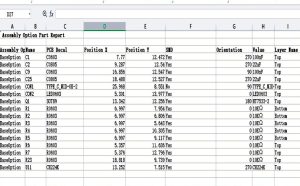
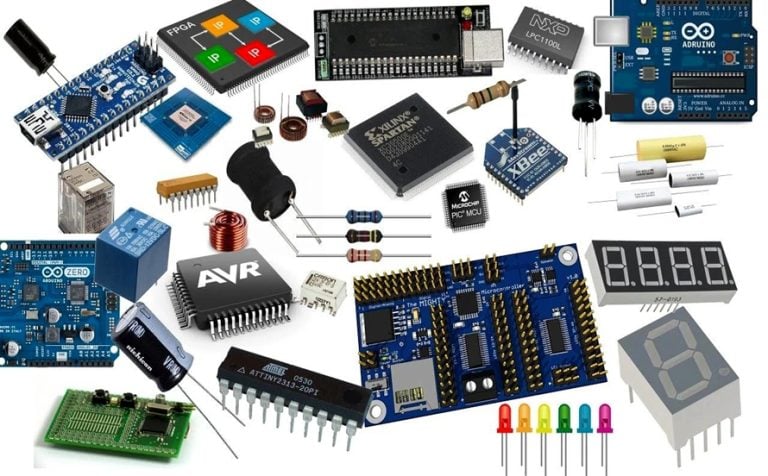
The exact BOM structure varies between manufacturers and organizations. However, a professional PCB BOM commonly includes the following information.
1. Reference Designator
The reference designator identifies the physical or logical position of a component in the PCB design.
Typical designators include:
- R1, R2, R3 – Resistors
- C1, C2, C3 – Capacitors
- L1, L2 – Inductors
- D1, D2 – Diodes
- U1, U2 – Integrated circuits
- Q1, Q2 – Transistors
- J1, J2 – Connectors
The reference designator should correspond to the schematic and PCB layout.
2. Manufacturer Part Number
The Manufacturer Part Number (MPN) uniquely identifies a specific component supplied by a particular manufacturer.
For example, two capacitors may have the same capacitance and voltage rating but differ in:
- Package size
- Dielectric material
- Tolerance
- Temperature rating
- Manufacturer
- Reliability characteristics
Therefore, specifying only the component value may not be sufficient for production.
3. Internal Part Number
Many companies assign their own internal part numbers to components.
An internal part number can simplify:
- ERP management
- Purchasing
- Inventory control
- Engineering change management
- Production tracking
This number can be linked to the manufacturer’s part number and approved supplier information.
4. Component Description
The BOM should provide a concise description of each component.
For example:
- 10 kΩ resistor, ±1%, 0603
- 100 nF ceramic capacitor, 50 V, 0402
- MCU, ARM Cortex-M series, QFN package
- USB Type-C connector, SMT
The description provides a quick reference for engineering and procurement teams.
5. Quantity
The BOM should specify the number of each component required for one PCB assembly.
For mass production, the required purchasing quantity can then be calculated according to the production order.
It is also important to distinguish between:
- Quantity per assembly
- Production quantity
- Purchasing quantity
- Recommended spare quantity
6. Component Type
Components can be classified according to their assembly technology and function.
Common classifications include:
- SMD components
- Through-hole components
- Integrated circuits
- Passive components
- Connectors
- Electromechanical components
- Mechanical components
Classification can help procurement and assembly teams organize production more efficiently.
7. Supplier Information
A professional BOM may also include supplier information such as:
- Supplier name
- Supplier part number
- Approved vendor
- Contact information
- Purchasing source
- Lead time
- Minimum order quantity
Supplier information becomes particularly important when components have long lead times or limited availability.
8. Component Specifications
Depending on the project, the BOM may include detailed electrical and mechanical specifications such as:
- Resistance
- Capacitance
- Inductance
- Voltage rating
- Current rating
- Power rating
- Tolerance
- Package size
- Temperature range
- Material
- Polarity
- RoHS status
These specifications help ensure that the correct component is selected during procurement.
9. Packaging and Storage Materials
Some PCBA projects require additional packaging and handling materials, including:
- Moisture barrier bags
- Desiccants
- ESD-safe packaging
- Trays
- Labels
- Protective materials
These items may be included in the BOM when they are part of the finished product or manufacturing process.
10. Other Manufacturing Materials
Depending on the assembly process, a BOM may also contain production-related materials such as:
- Solder materials
- Adhesives
- Coatings
- Labels
- Thermal interface materials
- Mechanical hardware
Not every BOM needs to contain all of these items. The required structure should be defined according to the project’s manufacturing process.
How to Create a PCB BOM
Creating an accurate BOM requires more than exporting a component list from PCB design software. The information should be reviewed and validated before it is released for production.
Step 1: Identify All Components
Start by identifying every component required by the approved schematic and PCB layout.
The component list can generally be exported from PCB design software such as Altium Designer, Cadence, KiCad, or other EDA platforms.
Make sure that every component has:
- A reference designator
- A component value or description
- A footprint
- A manufacturer part number where required
- Appropriate sourcing information
Step 2: Verify Component Information
BOM verification is one of the most important steps before production.
Check whether:
- The MPN is correct
- The package matches the PCB footprint
- Electrical specifications meet the design requirements
- The component is currently available
- The selected supplier is approved
- The component has not been discontinued
- Alternative components are properly qualified
This verification is especially important for high-density, multilayer, automotive, medical, industrial, and other reliability-sensitive PCB assemblies.
Step 3: Check the BOM Against the PCB Design
The BOM should be consistent with the final PCB layout and schematic.
Engineers should verify:
Schematic ↔ PCB Layout ↔ BOM ↔ Assembly Documentation
For example, if the BOM specifies one package while the PCB footprint corresponds to another package, the assembly process may fail even though the BOM itself appears complete.
Step 4: Standardize the BOM Format
Different manufacturers may use different BOM templates. A standardized format makes information easier to interpret and process.
A typical BOM may include columns such as:
| Reference | Quantity | Description | Manufacturer | MPN | Supplier | Package | Notes |
|---|---|---|---|---|---|---|---|
| R1-R10 | 10 | 10 kΩ resistor, ±1% | Manufacturer A | XXXXX | Supplier A | 0603 | Approved |
| C1-C8 | 8 | 100 nF, 50 V ceramic capacitor | Manufacturer B | XXXXX | Supplier B | 0402 | RoHS |
| U1 | 1 | Microcontroller | Manufacturer C | XXXXX | Supplier C | QFN | Main IC |
| J1 | 1 | USB Type-C connector | Manufacturer D | XXXXX | Supplier D | SMT | See drawing |
The exact columns should be adjusted according to the requirements of the PCB Manufacturing and assembly partner.
Step 5: Validate the Final BOM
Before releasing the BOM, conduct a final engineering and procurement review.
Important checks include:
- Component count
- Reference designators
- MPN accuracy
- Package compatibility
- Quantity
- Approved suppliers
- Component availability
- Substitute components
- Revision information
- Special assembly requirements
Step 6: Release and Control the BOM
Once the BOM has been approved, it should be formally released as a controlled manufacturing document.
A revision system should record changes caused by:
- Component substitutions
- Component shortages
- End-of-life notifications
- Design modifications
- Quantity changes
- Supplier changes
- Cost optimization
- Regulatory requirements
A controlled BOM prevents outdated component information from being accidentally used during production.
PCB BOM Revision Control
Revision control is especially important for products manufactured over a long period.
For example, a component may become obsolete several months after the original PCB design is released. The engineering team may then approve a replacement component.
Instead of simply overwriting the original BOM, the organization should record the change through an Engineering Change Order (ECO), Engineering Change Notice (ECN), or another controlled change-management process.
A properly controlled BOM should make it possible to determine:
- Which version was used
- When the change was made
- Why the change was made
- Which component was replaced
- Who approved the change
- Which production batches are affected
This traceability is particularly valuable for regulated or high-reliability applications.
PCB BOM vs Gerber Files
Gerber files and BOM files serve different purposes in PCB production.
| Item | PCB BOM | Gerber Files |
|---|---|---|
| Main purpose | Define components and materials | Define PCB fabrication geometry |
| Used for | PCB assembly and procurement | Bare PCB manufacturing |
| Component information | Yes | Generally no |
| Copper layers | No | Yes |
| Solder mask data | No | Yes |
| Silkscreen data | No | Yes |
| Component quantities | Yes | No |
| Component purchasing data | Yes | No |
| Assembly information | Yes, when properly structured | Limited |
Neither document completely replaces the other. For a complete PCBA manufacturing package, the BOM must be used together with the appropriate PCB fabrication and assembly data.
Common PCB BOM Problems
Several BOM issues can create manufacturing delays or assembly problems.
Incomplete Part Numbers
A BOM that lists only “10 kΩ resistor” may not provide enough information to select the correct component.
The manufacturer, tolerance, package, power rating, voltage rating, and other relevant specifications may also be necessary.
Incorrect Footprint
The physical package specified in the BOM must match the PCB footprint.
An incorrect package can result in:
- Assembly defects
- Soldering problems
- Component placement errors
- Mechanical interference
Obsolete Components
Using discontinued or obsolete components can create serious sourcing problems during production.
Engineers should check component lifecycle status and consider qualified alternatives where appropriate.
Incorrect Quantities
Incorrect quantities can cause material shortages or unnecessary purchasing costs.
The BOM should be reviewed against the actual production quantity and assembly requirements.
Uncontrolled Substitutions
A purchasing team should not replace a specified component solely because another component has the same basic electrical value.
Any substitute should be evaluated against the relevant electrical, mechanical, thermal, reliability, regulatory, and availability requirements.
PCB BOM Best Practices
For reliable PCB Manufacturing and PCBA production, consider the following best practices:
- Use consistent BOM templates across projects.
- Include complete manufacturer part numbers.
- Match every BOM item with the correct PCB footprint.
- Separate approved alternatives from the primary component.
- Record component lifecycle and availability information.
- Include revision and release status.
- Maintain strict BOM version control.
- Cross-check the BOM against schematic and PCB layout data.
- Identify special assembly requirements clearly.
- Review BOM changes through a controlled engineering process.
- Communicate approved revisions to procurement and manufacturing teams.
- Keep historical BOM versions for traceability.
How Kingda Supports PCB Manufacturing and Assembly
A reliable manufacturing partner needs accurate production documentation to transform an electronic design into a consistent physical product.
At Kingda, the BOM can be reviewed together with PCB fabrication and assembly data to identify potential issues before production begins. Engineering teams can evaluate component specifications, package information, sourcing requirements, and assembly considerations as part of the overall manufacturing process.
A well-prepared manufacturing package helps reduce:
- Component procurement errors
- Production delays
- Assembly mistakes
- Engineering changes
- Material shortages
- Manufacturing risks
The earlier BOM-related issues are identified, the easier it is to correct them before they affect production.
Final Summary
A PCB Bill of Materials (BOM) is one of the most important documents in the transition from PCB Design to PCB assembly and production. It provides the component information needed for procurement, inventory management, cost estimation, assembly, troubleshooting, and production planning.
An effective BOM should contain accurate reference designators, quantities, manufacturer part numbers, component specifications, package information, supplier details, and revision information. It should also remain synchronized with the schematic, PCB layout, Gerber files, assembly drawings, and other manufacturing documents.
For successful PCB Manufacturing, BOM accuracy and revision control are just as important as the physical PCB design itself. By maintaining a complete, standardized, and controlled BOM, engineering and manufacturing teams can reduce production risks, improve material management, and establish a more reliable PCBA manufacturing workflow.