Common PCB Components: Types, Functions & PCB Design and PCB Manufacturing Guide
A functional printed circuit board consists of a PCB substrate and a variety of electronic components. Although PCBs are available in many different types and configurations, the components mounted on them are equally diverse. Each component performs a specific electrical or mechanical function, and selecting the right components is essential for reliable PCB assembly.
Modern electronic products use hundreds or even thousands of components, depending on their functionality and complexity. Smartphones, computers, medical devices, telecommunications equipment, automotive electronics, industrial controllers, and consumer products all rely on carefully selected PCB components.
This article introduces some of the most commonly used electronic components in PCB assembly, explains their basic functions, and discusses how they are typically integrated into modern PCB Design and PCB Manufacturing.
What Are PCB Components?
PCB components are electronic or electromechanical devices mounted on a printed circuit board to create a functional electronic circuit. Components can be mounted using Surface Mount Technology (SMT), through-hole technology (THT), or a combination of both.
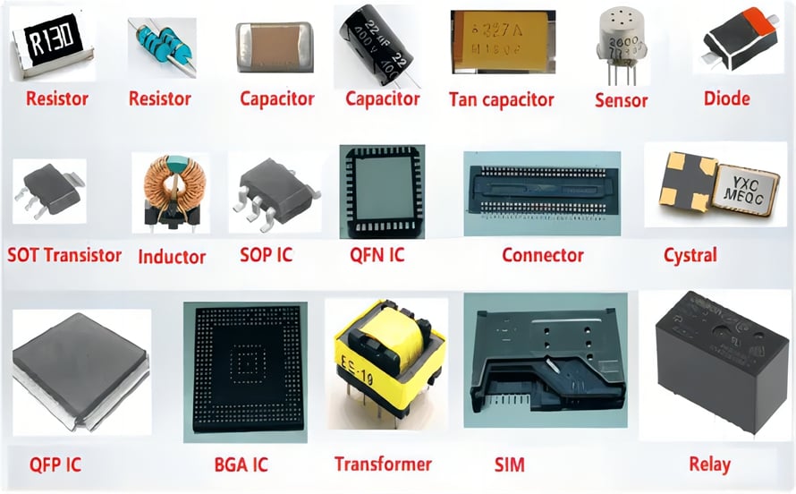
Common PCB components include:
- Resistors
- Capacitors
- Diodes
- Inductors
- Transistors
- Sensors
- Connectors
- Transformers
- Relays
- Integrated circuits (ICs)
Depending on the application, a PCB may also contain oscillators, switches, fuses, antennas, crystals, LEDs, potentiometers, batteries, and other specialized devices.
The component selection process considers electrical specifications, package size, power requirements, operating temperature, reliability, availability, cost, and assembly requirements.
1. Resistors
A resistor is one of the most fundamental components used in electronic circuits. Its primary function is to provide a controlled amount of electrical resistance, thereby limiting current and establishing desired voltage or current relationships within a circuit.
Resistors can be used for:
- Current limiting
- Voltage division
- Signal conditioning
- Biasing
- Pull-up and pull-down networks
- Termination
- Feedback circuits
- Power dissipation
Because resistors are relatively simple and inexpensive, they are found in almost every type of PCB assembly.
In a typical bill of materials (BOM), resistors are commonly identified with the reference designator R, such as R1, R2, and R10. Their values are normally specified in ohms (Ω), with common units including kΩ and MΩ.
Resistors are available in many package sizes and specifications. Standard chip resistors are inexpensive, while precision, high-power, high-voltage, or specialized resistor types can cost considerably more.
When preparing a PCB assembly quotation, engineers and purchasing teams should consider not only the unit price but also tolerance, power rating, package, availability, and lifecycle status.
2. Capacitors
A capacitor is another essential component in virtually every electronic product. It stores electrical energy in an electric field and can perform several important functions within a circuit.
Capacitors are commonly used for:
- Power-supply decoupling
- Noise filtering
- DC blocking
- Energy storage
- Signal coupling
- Timing circuits
- Voltage stabilization
- Transient suppression
Common capacitor types include:
- Ceramic capacitors
- Aluminum electrolytic capacitors
- Tantalum capacitors
- Film capacitors
- Polymer capacitors
- Mica capacitors
- Glass capacitors
- Supercapacitors
In a BOM, capacitors are generally identified using the reference designator C, such as C1, C2, or C15.
Multilayer ceramic capacitors (MLCCs) are particularly common in compact electronic products because they are small, reliable, and available in a wide range of capacitance and voltage ratings.
However, some specialized capacitors can be significantly more expensive than standard ceramic capacitors. Therefore, capacitance, voltage rating, tolerance, dielectric type, package size, and component availability should all be considered during PCB Design and cost estimation.
3. Diodes
A diode is a semiconductor component with two terminals that primarily allows current to flow more readily in one direction than the other.
Diodes are widely used for:
- Rectification
- Reverse-polarity protection
- Voltage regulation
- Signal detection
- Switching
- Clamping
- Transient protection
- Light emission
There are many types of diodes, including:
- Standard PN-junction diodes
- Rectifier diodes
- Zener diodes
- Schottky diodes
- Varactor diodes
- Light-emitting diodes (LEDs)
- TVS diodes
- Photodiodes
Diodes are among the most common semiconductor components used in PCB assembly, together with transistors and integrated circuits.
During assembly, polarity must be carefully controlled because many diode types are directional devices. Incorrect orientation can prevent the circuit from functioning or potentially damage other components.
4. Inductors
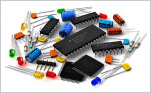
An inductor is a passive electronic component that stores energy in a magnetic field when current flows through it.
A typical inductor consists of conductive wire wound around a core or formed into a suitable geometry. The core may be made from materials such as ferrite, powdered iron, or other magnetic materials, depending on the intended application.
Inductors are commonly used for:
- Power conversion
- Filtering
- Energy storage
- EMI suppression
- RF circuits
- Signal filtering
- Impedance matching
Inductors can be classified according to their construction, core material, inductance value, current rating, frequency characteristics, and application.
Common PCB inductor types include:
- Wire-wound inductors
- Multilayer inductors
- Ferrite-core inductors
- Power inductors
- RF inductors
- Shielded inductors
A common mistake is to confuse inductors with transistors. A transistor is a semiconductor device primarily used for switching or amplification, whereas an inductor is a passive component that stores energy magnetically.
In PCB Design, engineers must consider inductance, saturation current, DC resistance, self-resonant frequency, thermal characteristics, and physical dimensions when selecting an inductor.
5. Transistors
A transistor is a semiconductor device used primarily for switching, amplification, signal control, and power management.
Transistors are fundamental building blocks of modern electronics and are commonly found throughout PCB assembly.
Major transistor families include:
- Bipolar junction transistors (BJTs)
- MOSFETs
- JFETs
- IGBTs
- Other specialized transistor structures
Depending on the application, a transistor can function as an electronic switch, amplifier, current-control device, or power-management component.
Transistors vary considerably in terms of:
- Voltage rating
- Current rating
- Power dissipation
- Switching speed
- Gain
- Frequency range
- Package type
- Thermal performance
For example, MOSFETs are widely used in power supplies, motor controllers, battery-management systems, automotive electronics, and switching circuits.
Proper transistor selection is particularly important in high-power PCB Manufacturing, where thermal management and PCB copper design can have a significant effect on reliability.
6. Sensors
Sensors detect physical or environmental conditions and convert them into electrical signals that can be processed by an electronic system.
Depending on the sensor technology, a PCB can detect parameters such as:
- Temperature
- Pressure
- Humidity
- Light
- Position
- Motion
- Acceleration
- Speed
- Sound
- Force
- Radiation
- Gas concentration
Common sensor categories include:
- Temperature sensors
- Pressure sensors
- Humidity sensors
- Position sensors
- Accelerometers
- Gyroscopes
- Optical sensors
- Proximity sensors
- Motion sensors
- Magnetic sensors
Sensors are particularly important in automotive electronics, medical devices, industrial automation, IoT equipment, smartphones, and smart-home products.
Sensor components may be sensitive to moisture, electrostatic discharge (ESD), contamination, mechanical stress, and excessive heat. Therefore, component handling and assembly conditions must be controlled carefully.
For certain sensor applications, the PCB layout itself can also affect measurement accuracy. Engineers may need to consider grounding, noise isolation, thermal gradients, trace routing, mechanical stress, and electromagnetic interference during PCB Design.
7. Connectors
Connectors provide detachable or semi-permanent electrical and mechanical connections between PCBs, cables, wires, modules, and other electronic assemblies.
Common PCB connector types include:
- Board-to-board connectors
- Wire-to-board connectors
- Cable connectors
- Pin headers
- Socket connectors
- Card-edge connectors
- Coaxial connectors
- Power connectors
- High-speed connectors
Small connectors can often be mounted directly onto a PCB using SMT. However, connectors subjected to frequent mating cycles or significant mechanical forces may require through-hole mounting or mechanical reinforcement.
Connector selection depends on:
- Current rating
- Voltage rating
- Signal frequency
- Contact resistance
- Mating cycles
- Mechanical strength
- Pitch
- Package dimensions
- Environmental conditions
For high-speed applications, connector geometry and impedance characteristics can directly influence signal integrity. Therefore, connector selection should be considered together with the PCB stackup, trace routing, grounding, and impedance-control strategy.
8. Transformers
A transformer is a magnetic component that transfers electrical energy between windings through electromagnetic induction.
Transformers are commonly used to:
- Increase or decrease AC voltage
- Provide galvanic isolation
- Match impedance
- Transfer power
- Isolate signals
Transformers are particularly common in power supplies, industrial equipment, telecommunications, networking equipment, and other applications requiring electrical isolation or voltage conversion.
The appropriate transformer depends on the required voltage ratio, power rating, operating frequency, insulation requirements, winding configuration, efficiency, and physical size.
In power-oriented PCB assembly, transformer placement and thermal management are also important because larger magnetic components can affect PCB mechanical and thermal characteristics.
9. Relays
A relay is an electrically controlled switching device used to connect or disconnect a circuit.
Traditional electromechanical relays use an electromagnetic mechanism to operate electrical contacts, while solid-state relays use semiconductor devices instead of mechanical contacts.
Relays are commonly used for:
- Power switching
- Circuit isolation
- Automatic control
- Industrial automation
- Motor control
- Power management
- Protection systems
Relay selection depends on factors such as:
- Contact configuration
- Switching voltage
- Switching current
- Coil voltage
- Switching frequency
- Electrical isolation
- Mechanical dimensions
- Environmental conditions
Because relays may switch relatively high voltages or currents, PCB layout must provide adequate clearance and creepage distances where required by the applicable safety standards.
For power PCB assembly, engineers should also consider relay heat generation, contact arcing, mechanical vibration, and the required electrical isolation.
10. Integrated Circuits (ICs)
An integrated circuit (IC) is a semiconductor device that incorporates many electronic functions into a single package.
Rather than using individual discrete components for every function, an IC can integrate transistors, resistive structures, capacitive structures, and other semiconductor elements into a compact device.
ICs are often described as the functional “brains” of an electronic system, although their actual roles vary widely.
Common IC categories include:
- Microcontrollers (MCUs)
- Microprocessors (MPUs)
- Memory devices
- Power-management ICs
- Operational amplifiers
- Audio ICs
- Communication ICs
- Motor-driver ICs
- Analog-to-digital converters
- Digital-to-analog converters
- System-on-chip (SoC) devices
IC packages range from very small packages such as CSP and WLCSP to larger packages such as QFP, QFN, and BGA.
BGA and other fine-pitch packages require particularly careful stencil design, placement accuracy, reflow control, and inspection. Because many solder joints are located underneath the package, X-ray inspection may be used when appropriate.
IC selection can also have a major impact on PCB Design, including power distribution, signal integrity, thermal management, layer count, routing density, and component placement.
How PCB Components Are Identified
During PCB Design and assembly, reference designators make it easier to identify individual components.
Common reference designators include:
| Component | Typical Reference Designator |
|---|---|
| Resistor | R |
| Capacitor | C |
| Inductor | L |
| Diode | D |
| Transistor | Q |
| Integrated Circuit | U |
| Connector | J / P |
| Transformer | T |
| Relay | K |
| Crystal/Oscillator | Y / X |
| Fuse | F |
The exact reference-designator convention can vary depending on the design standard, CAD library, and engineering organization.
These identifiers are used across PCB design files, schematics, BOMs, assembly drawings, and inspection documentation, helping engineers and manufacturers maintain traceability throughout the production process.
SMT and Through-Hole PCB Components
PCB components can generally be installed using SMT, through-hole technology (THT), or both.
SMT Components
SMT components are mounted directly onto PCB pads without requiring conventional component leads to pass through the board.
Advantages include:
- Compact package sizes
- High component density
- Efficient automated assembly
- Reduced PCB area
- Suitability for high-volume production
Through-Hole Components
Through-hole components have leads that pass through drilled holes in the PCB and are soldered to the board.
They are often selected when greater mechanical strength, higher power handling, or stronger mechanical connections are required.
Many modern products combine both technologies. This mixed-technology approach allows designers to select the most appropriate mounting method for each component.
How Component Selection Affects PCB Manufacturing
Selecting a PCB component involves more than checking its electrical value.
Engineers should consider:
Electrical Specifications
Voltage, current, resistance, capacitance, inductance, frequency, tolerance, power rating, and other electrical parameters must meet the circuit requirements.
Package and Footprint
The physical package must correspond to the PCB footprint and assembly process. An incorrect footprint can result in poor solder joints, component misalignment, or assembly failure.
Thermal Performance
Power components such as MOSFETs, regulators, LEDs, and power resistors can generate significant heat. Thermal vias, copper areas, heatsinks, and appropriate component placement may be required.
Availability
Component availability can directly affect production schedules. Engineers should consider lifecycle status, lead times, approved alternatives, and supply-chain risks.
Cost
Component cost can have a significant impact on total PCB assembly cost, especially for products containing large quantities of components.
Reliability
For automotive, medical, aerospace, industrial, and other demanding applications, components may need to meet additional reliability, environmental, qualification, or regulatory requirements.
Conclusion
A modern PCB is much more than a piece of fiberglass and copper. It is a complete electronic platform that combines a wide range of PCB components to perform specific electrical, mechanical, sensing, control, and power-management functions.
Resistors, capacitors, diodes, inductors, transistors, sensors, connectors, transformers, relays, and integrated circuits are among the most commonly used components in electronic products. Each component has different electrical characteristics, package options, mounting requirements, and reliability considerations.
Successful PCB Design therefore requires careful component selection and accurate footprints, while successful PCB Manufacturing depends on matching those design decisions with appropriate assembly processes, inspection methods, and quality controls.
By understanding the function and characteristics of common PCB components, engineers can create more reliable designs, simplify assembly, improve manufacturability, and support the long-term performance of electronic products.
Article Summary
PCB components are the building blocks that give a printed circuit board its electrical and functional capabilities. Common components include resistors, capacitors, diodes, inductors, transistors, sensors, connectors, transformers, relays, and ICs.
Each component has a specific role, and its electrical specifications, package, footprint, thermal characteristics, availability, cost, and reliability should be considered during PCB Design. Proper component selection also helps improve the efficiency, quality, and reliability of PCB Manufacturing and PCB assembly.