PCB Resistors: PCB Design, PCB Manufacturing, Types, Uses & Selection Guide
Resistors are among the most fundamental components used in virtually every electronic circuit. A typical printed circuit board (PCB) combines active components, such as transistors and integrated circuits (ICs), with passive components, including resistors, capacitors, and inductors.
Although PCB designers must consider resistor values, power ratings, tolerances, footprints, and placement during the design process, the role of a resistor extends far beyond simply “reducing current.” Resistors are used for current limiting, voltage division, signal termination, transistor biasing, pull-up and pull-down functions, sensing, filtering, and many other circuit functions.
The basic relationship between voltage, current, and resistance is described by Ohm’s Law (V = IR). This fundamental relationship helps engineers calculate the current flowing through a resistor and determine an appropriate resistance value and power rating.
This article explains what PCB resistors are, how they work, the major types of resistors, how to identify them on a circuit board, common applications, resistor selection considerations, common failure modes, and how resistors are soldered during PCB assembly.
What Is a PCB Resistor?

A PCB resistor is a two-terminal passive electronic component that provides a defined amount of electrical resistance in a circuit.
When current flows through a resistor, the resistor produces a voltage drop according to Ohm’s Law:
V = I × R
Where:
- V = voltage across the resistor
- I = current through the resistor
- R = resistance in ohms (Ω)
Resistors are used to control current and establish desired voltage levels within a PCB circuit.
For example, a resistor can limit current through an LED, establish the bias point of a transistor, create a reference voltage for an analog circuit, or terminate a high-speed signal.
PCB resistors are commonly connected using either:
- Through-Hole Technology (THT)
- Surface-Mount Technology (SMT)
Through-hole resistors have leads that pass through drilled holes in the PCB, while surface-mount resistors are soldered directly onto copper pads on the PCB surface.
Because of their simple construction, low cost, small size, and wide range of available resistance values, resistors are essential components in almost every category of electronic equipment.
Main Functions of PCB Resistors
Resistors perform many different functions in PCB Design. The appropriate resistor configuration depends on the electrical requirements of the circuit.
1. Voltage Division
Two or more resistors can be connected in series to create a voltage divider.
For two resistors, the output voltage can be calculated as:
Vout = Vin × R2 / (R1 + R2)
This configuration is commonly used to generate a lower reference voltage from a higher supply voltage.
Typical applications include:
- Sensor interfaces
- Analog input circuits
- Reference voltage generation
- ADC input scaling
- Level-shifting circuits
For example, a properly designed resistor divider can reduce a 5 V signal to a voltage suitable for a 3.3 V input. The resistor values must be selected according to the input impedance and operating requirements of the receiving circuit.
2. LED Current Limiting
LEDs require controlled current. Connecting an LED directly to an ideal voltage source without appropriate current limiting can result in excessive current and damage the LED.
A series resistor can limit the LED current.
A simplified calculation is:
R = (Vsupply − VLED) / ILED
For example, if the supply voltage is 5 V, the LED forward voltage is 2 V, and the desired current is 10 mA:
R = (5 − 2) / 0.01 = 300 Ω
The nearest standard resistor value can then be selected while considering LED brightness, resistor power dissipation, and component tolerances.
3. Heat Generation
Electrical energy dissipated by a resistor is converted into heat.
The resistor power can be calculated using:
P = V × I
Other useful forms include:
P = I²R
and
P = V²/R
Resistors intentionally designed to dissipate significant power are used in applications such as:
- Power supplies
- Load banks
- Braking circuits
- Heaters
- Current-sensing systems
- Power management circuits
The selected resistor must have an adequate power rating and suitable thermal environment.
4. Signal Termination and Impedance Matching
Resistors are frequently used for signal termination in high-speed digital and analog circuits.
A termination resistor can help control reflections caused by impedance discontinuities in transmission lines.
This is particularly important for:
- High-speed digital interfaces
- RF circuits
- Communication systems
- Differential signaling
- Clock networks
However, impedance matching is not simply a matter of adding a resistor. The PCB stackup, trace impedance, driver impedance, receiver characteristics, transmission-line length, and termination topology must all be considered during PCB Design.
Types of PCB Resistors
Resistors can be classified in several ways, including fixed versus variable resistance, linear versus nonlinear behavior, and specialized sensing functions.
1. Fixed Resistors
A fixed resistor has a predetermined resistance value that is not intended to be adjusted during normal operation.
Common applications include:
- Current limiting
- Voltage division
- Pull-up and pull-down circuits
- Signal termination
- Transistor biasing
- LED protection
Fixed resistors are available in many resistance values, package sizes, tolerance levels, and power ratings.
2. Variable Resistors
A variable resistor allows the resistance value to be adjusted mechanically.
Two common types are potentiometers and rheostats.
Potentiometer
A potentiometer is typically a three-terminal adjustable resistor used as a voltage divider.
Common applications include:
- Volume controls
- User-adjustable settings
- Calibration
- Analog control interfaces
Rheostat
A rheostat is generally used as a two-terminal variable resistor to control current or adjust resistance within a circuit.
3. Trimmer Resistors
A trimmer potentiometer, or trimmer resistor, is a small adjustable component designed primarily for calibration rather than frequent user adjustment.
Trimmers are commonly used during manufacturing or servicing to fine-tune:
- Sensor thresholds
- Gain
- Offset
- Reference voltage
- Calibration parameters
4. Thermistors
A thermistor is a resistor whose resistance changes significantly with temperature.
The two primary types are:
- NTC thermistors: Resistance decreases as temperature increases.
- PTC thermistors: Resistance increases as temperature increases over the relevant operating range.
Thermistors are widely used for:
- Temperature sensing
- Overcurrent protection
- Inrush-current limiting
- Thermal monitoring
Therefore, it is not technically correct to state that every thermistor decreases in resistance as temperature rises.
5. Photoresistors
A photoresistor, also called a light-dependent resistor (LDR), changes its resistance according to the intensity of incident light.
In a typical photoresistor, resistance decreases as light intensity increases.
Applications include:
- Light detection
- Automatic lighting systems
- Optical sensors
- Ambient-light measurement
How to Identify Resistors on a PCB
Resistors on a PCB are generally found in either through-hole or surface-mount packages.
Understanding their physical appearance and markings helps engineers, technicians, and repair personnel identify the correct component.
Through-Hole Resistors
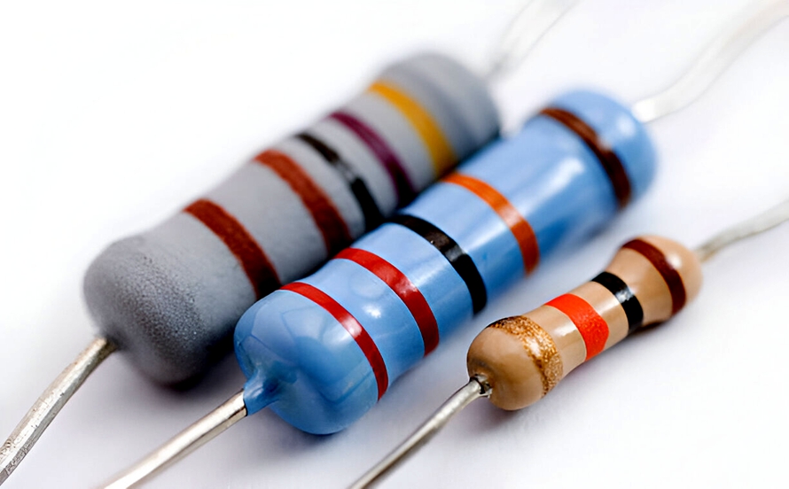
Traditional through-hole resistors typically have colored bands printed around their cylindrical bodies.
The most common resistor color-code systems include:
- 4-band resistors
- 5-band resistors
- 6-band resistors
For a typical four-band resistor:
- First band = first significant digit
- Second band = second significant digit
- Third band = multiplier
- Fourth band = tolerance
For example, a resistor with a red, red, brown, and gold sequence represents:
22 × 10¹ Ω = 220 Ω ±5%
The color code should be read in the correct orientation. The tolerance band is commonly spaced slightly farther from the other bands, but component markings and manufacturer conventions should be considered when identification is uncertain.
SMD Resistors
Surface-mount resistors are typically small rectangular components with metallic terminations on both ends.
Common packages include:
- 0201
- 0402
- 0603
- 0805
- 1206
- 1210
Package dimensions vary by manufacturer and standard convention.
Larger SMD resistors may have numerical markings, while very small components may have no visible marking.
SMD resistors are commonly installed using automated pick-and-place equipment followed by reflow soldering.
This makes them particularly suitable for high-density PCB Manufacturing and automated SMT assembly.
PCB Resistor Applications
Resistors are used in almost every category of electronic circuit.
1. Current Limiting and Protection
A resistor can limit current flowing into sensitive components.
For example:
LED protection
A series resistor limits LED current to a calculated operating value.
Transistor base drive
A resistor can limit the current supplied to a transistor base in a basic BJT switching circuit.
The exact resistor value depends on the transistor characteristics, drive voltage, load, switching requirements, and circuit topology.
2. Voltage Divider Networks
Voltage-divider circuits allow designers to obtain a proportional voltage from a larger supply.
Common applications include:
- ADC input scaling
- Sensor interfaces
- Reference circuits
- Feedback networks
- Analog signal conditioning
A resistor divider should be designed with consideration for the input impedance of the circuit connected to its output.
3. Bias Networks
Resistors are frequently used to establish the DC operating point of transistors and analog circuits.
A properly designed bias network can help maintain an appropriate operating point despite changes in supply voltage, temperature, and device characteristics.
Applications include:
- BJT amplifiers
- MOSFET circuits
- Operational amplifier circuits
- Analog signal-processing systems
4. Pull-Up and Pull-Down Resistors
Digital circuits frequently use pull-up and pull-down resistors to establish a defined logic state when a signal is otherwise floating.
They are commonly found in:
- Microcontroller circuits
- I²C interfaces
- Reset circuits
- Switch inputs
- Open-drain/open-collector circuits
5. Signal Termination
Termination resistors can reduce signal reflections in high-speed transmission lines.
The correct termination method depends on the interface and transmission-line topology.
Examples include:
- Series termination
- Parallel termination
- Thevenin termination
- Differential termination
6. Current Sensing
A low-value precision resistor, commonly called a shunt resistor, can be used to measure current.
By measuring the voltage across the resistor:
I = V / R
the circuit can calculate the current flowing through the monitored path.
Current-sense resistors are widely used in:
- Battery management systems
- Motor controllers
- Power supplies
- DC-DC converters
- Battery chargers
Common PCB Resistor Problems and Solutions
Although resistors are relatively simple components, they can fail due to electrical overstress, excessive temperature, mechanical stress, moisture, contamination, and manufacturing defects.
1. Resistor Overheating
If a resistor continuously dissipates more power than its rated capacity, its temperature can rise excessively.
Possible consequences include:
- Resistance drift
- Discoloration
- Cracking
- Open-circuit failure
- Damage to nearby components
- PCB discoloration or delamination in severe cases
The solution is to select an appropriate power rating and provide adequate thermal management.
Designers often apply a power derating margin rather than operating a resistor continuously at its absolute maximum rating.
2. Thermal Stress and Solder-Joint Cracking
PCB assemblies experience temperature changes during:
- Reflow soldering
- Power cycling
- Environmental temperature changes
- Thermal testing
Different materials have different coefficients of thermal expansion (CTE). Repeated thermal cycling can therefore place mechanical stress on solder joints and PCB structures.
Possible symptoms include:
- Intermittent connections
- Increased contact resistance
- Open circuits
- Random system resets
Appropriate component selection, PCB material selection, solder-joint design, and thermal-cycle validation can help reduce these risks.
3. Resistance Drift
Long-term exposure to excessive temperature, electrical overstress, humidity, or other environmental conditions can cause the resistance value to change.
Resistance drift can be particularly important in:
- Precision analog circuits
- Measurement systems
- Reference circuits
- Feedback networks
- Sensor interfaces
Selecting resistors with appropriate tolerance, temperature coefficient, power rating, and long-term stability is essential.
4. Mechanical Cracking
Small SMD resistors can be damaged by excessive PCB bending, board flexing, mechanical shock, or improper depanelization.
This is particularly important for:
- Large ceramic packages
- Rigid-flex PCBs
- Thin PCBs
- Automotive electronics
- Portable electronics
PCB layout and assembly processes should minimize unnecessary mechanical stress around sensitive components.
5. Incorrect Resistor Value
Incorrect resistor values can result from:
- Wrong BOM information
- Component substitution
- Assembly errors
- Incorrect color-code interpretation
- Manufacturing defects
Proper BOM management, automated component verification, AOI, and electrical testing can reduce the risk.
How to Select the Right PCB Resistor
Choosing a resistor is not simply a matter of finding the required resistance value.
Several electrical, mechanical, thermal, and manufacturing parameters should be evaluated.
1. Resistance Value
The resistance value must meet the circuit requirement.
For a simple resistive circuit, Ohm’s Law provides:
R = V / I
For more complex circuits, the required resistance should be calculated based on the complete circuit topology.
2. Power Rating
Calculate the expected power dissipation:
P = V²/R
or
P = I²R
The selected resistor should have an adequate power rating with an appropriate design margin.
3. Tolerance
Tolerance indicates how much the actual resistance can vary from its nominal value.
Common tolerance values include:
- ±1%
- ±5%
- ±10%
Precision applications may require tighter tolerances.
4. Temperature Coefficient
The temperature coefficient of resistance (TCR) indicates how resistance changes with temperature.
A low-TCR resistor is often preferred in precision circuits where resistance stability is important.
5. Package Size
The resistor package must match the PCB footprint and assembly process.
Smaller packages save PCB space but may have lower power-handling capability and can be more difficult to inspect or rework.
6. Operating Voltage
A resistor also has a maximum working-voltage limitation.
Even when calculated power dissipation is within the rated value, excessive voltage across a resistor can cause electrical overstress.
7. Environmental Conditions
Consider:
- Operating temperature
- Humidity
- Vibration
- Chemical exposure
- Mechanical stress
- Expected service life
Automotive, aerospace, medical, industrial, and outdoor electronics may require components with enhanced environmental reliability.
8. Resistor Type
The application determines whether the design requires:
- Fixed resistor
- Precision resistor
- Power resistor
- Current-sense resistor
- Thermistor
- Potentiometer
- Trimmer
- Photoresistor
9. Availability and Lifecycle
Component availability is also an important consideration in PCB Design.
Before finalizing a BOM, engineers should check:
- Manufacturer availability
- Lead time
- Minimum order quantity
- Lifecycle status
- Approved alternatives
- Supply-chain risks
Choosing a technically suitable resistor that becomes obsolete shortly after product launch can create unnecessary redesign costs.
How to Solder a Resistor on a PCB
Resistor soldering depends on whether the component is through-hole or surface mount.
Materials and Tools
For manual through-hole soldering, typical tools include:
- Temperature-controlled soldering iron
- Solder wire
- Flux, when appropriate
- Solder wick or desoldering pump
- Tweezers
- PCB holder
- Magnification equipment for small components
Appropriate ventilation and personal protective practices should also be followed.
Step 1 – Prepare the PCB
Make sure the PCB pads are clean and free of excessive contamination.
For through-hole resistors, insert the component leads through the appropriate holes and position the component correctly.
For SMD resistors, place the component on the prepared solder pads.
Step 2 – Preheat and Tin the Soldering Tip
Allow the soldering iron to reach the appropriate working temperature for the selected solder alloy and PCB assembly.
A small amount of solder on the tip can improve thermal transfer.
The goal is to heat the joint efficiently rather than applying excessive heat.
Step 3 – Solder the Component
For a through-hole resistor:
- Insert the resistor into the PCB.
- Slightly bend the leads if needed to hold the component in position.
- Heat the PCB pad and component lead simultaneously.
- Feed solder into the heated joint.
- Remove the solder and then the iron.
- Allow the joint to cool naturally.
The solder should form a smooth, properly wetted joint around the lead and pad.
For SMD resistors, manual soldering can be performed with a fine-tip iron and tweezers, while production assembly generally uses solder paste, stencil printing, pick-and-place equipment, and reflow soldering.
Step 4 – Inspect the Solder Joint
After the joint cools, inspect it for:
- Adequate solder coverage
- Good wetting
- Proper component placement
- Solder bridges
- Cracks
- Insufficient solder
- Excessive solder
For production PCB Manufacturing, inspection may include AOI and other quality-control processes.
PCB Resistors in PCB Design and PCB Manufacturing
Resistors may be small and inexpensive, but their correct selection and placement are essential to reliable PCB performance.
During PCB Design, engineers should consider resistance value, tolerance, power rating, temperature coefficient, package size, operating voltage, signal requirements, and component availability.
During PCB Manufacturing and PCB assembly, manufacturers must also control:
- Correct component placement
- Solder-paste printing
- Reflow profile
- Component polarity where applicable
- Solder-joint quality
- AOI inspection
- Electrical testing
For high-volume SMT production, automated component placement and inspection are particularly important because modern PCBs may contain hundreds or thousands of passive components.
Conclusion
PCB resistors are simple two-terminal passive components, but they perform some of the most important functions in electronic circuits.
They can limit current, divide voltage, establish bias conditions, terminate high-speed signals, provide pull-up and pull-down functions, measure current, sense temperature, and protect sensitive components.
Selecting the correct resistor requires more than calculating the resistance value. Engineers should also consider power dissipation, tolerance, temperature coefficient, package size, working voltage, environmental conditions, availability, and long-term reliability.
For reliable PCB Design and PCB Manufacturing, resistor selection should be considered together with PCB layout, thermal management, assembly technology, component sourcing, and electrical testing.
Understanding these factors allows engineers to build smaller, more reliable, and more manufacturable electronic products.
Article Summary
PCB resistors are essential passive components used for current limiting, voltage division, signal termination, biasing, sensing, and circuit protection. They are available in fixed, variable, precision, thermistor, photoresistor, and other specialized forms. During PCB Design, engineers must select resistors according to resistance, power rating, tolerance, TCR, package size, voltage rating, environmental conditions, and supply availability. During PCB Manufacturing, correct placement, soldering, inspection, and electrical testing are essential for reliable performance.