How to Identify PCB Components: PCB Design, PCB Manufacturing & Troubleshooting Guide
Every electronic device relies on a printed circuit board (PCB) to connect and manage its electronic components. A PCB can be viewed as a compact structural platform on which components are mounted and electrically interconnected.
Knowing how to identify PCB Components is an important skill for engineers, technicians, repair specialists, and electronics enthusiasts. Whether you are troubleshooting a faulty circuit, performing PCB reverse engineering, replacing a damaged component, or analyzing an unfamiliar board, accurate component identification is often the first step.
PCB component identification typically combines visual inspection, knowledge of common component markings, package recognition, electrical measurements, schematics, datasheets, and manufacturer documentation. By using these methods systematically, you can identify components more efficiently and understand their roles within the circuit.
This guide explains how to identify components on a PCB and how the process supports PCB Design, PCB Manufacturing, repair, testing, and troubleshooting.
What Are PCB Components?
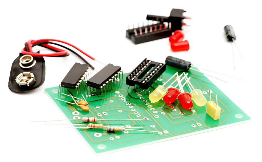
PCB Components are electronic devices mounted on a printed circuit board to perform specific electrical or functional tasks.
Common components include:
- Resistors
- Capacitors
- Inductors
- Diodes
- Transistors
- Integrated circuits (ICs)
- Crystals and oscillators
- Transformers
- Relays
- Connectors
- Fuses
- Switches
Different components perform different functions. Resistors control current and establish voltage relationships, capacitors store electrical energy and filter signals, inductors store energy in magnetic fields, and semiconductor devices control or rectify electrical signals.
Integrated circuits can contain thousands, millions, or even billions of semiconductor devices within a single package and can perform functions ranging from signal processing to power management and communication.
Without these components, a PCB would simply be a substrate with conductive copper structures rather than a functioning electronic system.
Understanding component types and functions is therefore essential for PCB Troubleshooting, repair, reverse engineering, and reliable circuit development.
Tools for Identifying PCB Components
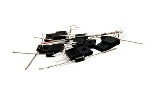
Identifying a component accurately often requires more than simply looking at its physical appearance. The following tools can make the process significantly easier.
Magnifying Glass or Microscope
Modern PCBs frequently use very small surface-mount components. Their markings may be difficult to read with the naked eye.
A magnifying glass can help with basic identification, while a microscope is useful for:
- Fine-pitch ICs
- Tiny SMD resistors
- Small capacitors
- Diode markings
- Package codes
- PCB reference designators
- Solder-joint inspection
Digital Multimeter
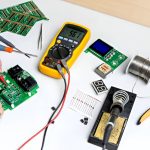
A digital multimeter (DMM) can help verify the electrical characteristics of many passive and semiconductor components.
Depending on the meter, you may be able to measure:
- Resistance
- Capacitance
- Voltage
- Current
- Continuity
- Diode forward voltage
Electrical measurements should be performed carefully because in-circuit measurements may be affected by other components connected to the same electrical network.
PCB Schematic
A schematic provides a logical representation of the circuit and shows how individual components are electrically connected.
When a schematic is available, it can help identify a component’s:
- Reference designator
- Electrical function
- Nominal value
- Connection points
- Part number
- Relationship with other components
A schematic is often one of the most reliable resources for identifying an unfamiliar component.
Component Datasheet
A datasheet provides detailed information about a specific electronic component.
Depending on the component, a datasheet may include:
- Part number
- Electrical characteristics
- Pin configuration
- Package type
- Absolute maximum ratings
- Operating conditions
- Recommended application circuits
- Mechanical dimensions
Datasheets are particularly important when a component marking alone is insufficient to determine the exact part.
Online Component Databases
Online technical resources can help identify components based on package markings, manufacturer codes, and part numbers.
When searching online, it is important to verify the result against the physical package and electrical characteristics rather than relying solely on a matching text code.
How to Identify PCB Components
Accurate component identification usually involves several steps. Combining multiple identification methods provides much better results than relying on a single characteristic.
1. Perform a Visual Inspection
Begin by carefully examining the PCB.
Look for printed reference designators, component markings, package shapes, polarity indicators, and visible electrical connections.
A PCB Reference Designator is an alphanumeric identifier printed on the PCB silkscreen to identify a particular component or circuit element.
Common reference designators include:
| Component | Typical Reference Designator |
|---|---|
| Resistor | R |
| Capacitor | C |
| Inductor | L |
| Transistor | Q |
| Diode | D |
| Integrated Circuit | U or IC |
| Switch | SW |
| Crystal/Oscillator | Y or X |
| Transformer | T |
| Fuse | F |
| Relay | K |
| Filter | FL |
| Motor | M |
| Power Supply | PS |
| Test Point | TP |
| LED | D or LED |
| Connector | J or CN |
The exact designation can vary between manufacturers and design standards, so reference designators should be used together with other identification methods.
For example, a marking such as R15 usually indicates the fifteenth resistor in the design, while C8 generally indicates the eighth capacitor.
Reference designators are especially useful when reading a schematic or PCB layout because they allow the physical component to be matched to its electrical representation.
2. Analyze Component Shape and Package Size
The physical appearance of a component provides another important identification clue.
Resistors
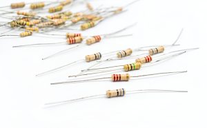
Through-hole resistors are often cylindrical and may have colored bands indicating their resistance value and tolerance.
Surface-mount resistors are typically small rectangular components. Some larger SMD resistors have printed numerical or alphanumeric markings, while very small resistors may have no visible marking.
Capacitors
Capacitors are available in many different packages.
Common examples include:
- Cylindrical aluminum electrolytic capacitors
- Small ceramic disc capacitors
- Rectangular multilayer ceramic capacitors
- Tantalum capacitors
- SMD polymer capacitors
The package alone may not reveal the exact capacitance or voltage rating, so markings and documentation should be checked when available.
Diodes
Diodes are commonly found in cylindrical, rectangular, or SMD packages.
Many diode packages include a stripe or other marking indicating the cathode.
However, the exact marking convention depends on the package and manufacturer.
Transistors
Transistors may use packages such as TO-92, TO-220, SOT-23, and many other surface-mount or through-hole formats.
A transistor’s package can provide a useful clue, but the exact part number should be confirmed using its marking and datasheet because many different devices can use the same package.
Integrated Circuits
ICs are commonly housed in black plastic packages with multiple terminals.
Typical packages include:
- SOIC
- QFN
- QFP
- TQFP
- DIP
- BGA
The number and arrangement of pins, package shape, orientation marking, and top-side code can help identify the device.
Inductors
Inductors can appear as:
- Wire coils
- Ferrite components
- Shielded rectangular packages
- Drum-core structures
- SMD power inductors
Larger power inductors are generally designed to handle higher currents, but their exact electrical specifications should always be confirmed from the manufacturer’s documentation.
Crystals and Oscillators
Quartz crystals are often housed in small metal or ceramic packages.
Oscillators may have similar physical dimensions but generally contain an active oscillator circuit rather than functioning as a passive crystal alone.
Because package appearance can be similar, checking the component marking is important.
3. Determine the Component Value
After identifying the general component type, determine its electrical value and rating.
Resistor Identification
Traditional through-hole resistors commonly use colored bands to indicate resistance and tolerance.
For example, an SMD resistor marked 103 generally represents:
10 × 10³ Ω = 10 kΩ
However, not all SMD resistor codes follow the same convention, and very small components may use different marking systems or remain unmarked.
Capacitor Identification
Ceramic and other capacitors may use numerical codes.
For example, the common three-digit code 104 generally represents:
10 × 10⁴ pF = 100 nF
The voltage rating may be indicated separately or may require reference to the part number or schematic.
For electrolytic capacitors, capacitance and voltage ratings are often printed directly on the body.
Inductor Identification
Inductors may use numerical or alphanumeric markings to indicate inductance.
For example, a marking such as 100 may represent 10 µH under a common three-digit coding convention. However, markings vary between manufacturers, so the manufacturer’s documentation should be consulted before making a final identification.
Diode Identification
Diodes typically use a part number or abbreviated marking.
The marking may identify the device family, electrical rating, package, or manufacturer-specific code.
The datasheet can then be used to verify parameters such as:
- Forward voltage
- Reverse voltage
- Forward current
- Power dissipation
- Switching speed
- Polarity
Transistor Identification
Transistor markings can identify the specific device or manufacturer part number.
For bipolar junction transistors (BJTs), the device may be an NPN or PNP transistor. MOSFETs may be identified as N-channel or P-channel devices.
The marking alone may not always provide enough information, so the datasheet should be used to verify the transistor type and electrical specifications.
Integrated Circuit Identification
ICs normally have a manufacturer marking, part number, or abbreviated top-side code.
The marking can be used to identify:
- Manufacturer
- Device family
- Exact part number
- Package
- Revision or date code
Once the part number has been identified, the datasheet can provide the pinout and functional description.
For example, a crystal or oscillator frequency may be printed directly on its package, while an IC may use a much shorter code that must be cross-referenced with manufacturer documentation.
4. Use the PCB Schematic
A schematic is one of the most valuable resources for identifying PCB components.
Unlike a photograph of the PCB, a schematic shows the electrical relationship between components.
Standard schematic symbols represent components such as:
- Resistors
- Capacitors
- Inductors
- Diodes
- Transistors
- Operational amplifiers
- ICs
- Switches
- Connectors
- Transformers
The schematic may also provide the component’s reference designator and nominal value.
For example, if you identify R12 on the PCB, you can locate R12 on the schematic and determine its electrical function and specified resistance.
This makes schematic analysis particularly valuable during PCB Troubleshooting, repair, and reverse engineering.
5. Check Component Documentation
Component documentation can provide information that cannot be determined through visual inspection alone.
When identifying an unfamiliar component, record as much information as possible, including:
- Top-side marking
- Package type
- Number of pins
- Pin arrangement
- Reference designator
- Manufacturer logo
- PCB location
- Nearby components
Then compare these details against manufacturer datasheets and reliable component databases.
For obsolete or discontinued components, archived datasheets and manufacturer documentation can be particularly useful.
6. Identify Component Polarity
Some PCB components are polarized and must be installed in the correct orientation.
Incorrect polarity can prevent a circuit from functioning and may cause component damage.
Common polarized components include:
- Electrolytic capacitors
- Tantalum capacitors
- Diodes
- LEDs
- Some ICs and semiconductor devices
PCB polarity markings may include:
-
- and − symbols
- Pin 1 indicators
- Cathode markings
- Anode markings
- Notches
- Dots
- Silkscreen outlines
For example, a diode often has a stripe indicating the cathode. An LED may have physical and PCB markings indicating its orientation.
For ICs, a notch or dot commonly identifies the package orientation and Pin 1 location.
Always verify polarity using the component datasheet when there is any uncertainty.
Why Accurate PCB Component Identification Matters
Accurate PCB Component Identification is more than simply determining what a component looks like.
It helps engineers understand:
- What the component does
- Where it is connected
- What electrical parameters it has
- Why it may have failed
- Which replacement component is appropriate
- How it affects the overall circuit
This information is essential during PCB repair and failure analysis.
For manufacturers, accurate component identification also supports PCB Manufacturing by helping engineers verify bills of materials (BOMs), assembly data, component placement, and production documentation.
During reverse engineering, component identification can help reconstruct a schematic and understand the functional architecture of an unfamiliar PCB.
Common Mistakes When Identifying PCB Components
Several mistakes can lead to incorrect identification.
Relying Only on Package Appearance
Different components can use identical or similar packages. A SOT-23 package, for example, can contain different types of transistors, diodes, regulators, and other semiconductor devices.
Package shape should therefore be treated as a clue rather than definitive proof.
Assuming a Marking Is the Full Part Number
Component markings can be abbreviated because of limited package space.
A short code may correspond to multiple possible components from different manufacturers.
Always verify the marking against the package, manufacturer, circuit function, and electrical characteristics.
Ignoring the Circuit Context
A component’s location on the PCB provides valuable information.
For example, a component positioned near a voltage regulator may serve a power-management function, while components surrounding a crystal may form part of a clock circuit.
Circuit context should support—not replace—datasheet verification.
Measuring Components Only In-Circuit
In-circuit measurements can be affected by parallel components and connected circuits.
For example, measuring the resistance of a resistor directly on the PCB may produce a value different from its nominal resistance because other circuit paths are connected in parallel.
When necessary, isolate the component or use an appropriate testing method.
Conclusion
Accurate PCB Component Identification is an essential skill for PCB design, manufacturing, repair, reverse engineering, and troubleshooting. By combining visual inspection, reference designators, package recognition, component markings, electrical measurements, schematics, and datasheets, engineers and technicians can identify unfamiliar components with much greater confidence.
The most reliable approach is to use multiple sources of evidence rather than relying on appearance or a single marking. This is especially important for small SMD components, semiconductor devices, and obsolete parts where identification codes may be abbreviated or ambiguous.
For professional electronics development, accurate component identification also contributes to better PCB Design, more reliable PCB Manufacturing, and more efficient PCB Troubleshooting. Kingda can support customers with professional PCB manufacturing and related technical services, helping transform reliable circuit designs into manufacturable and functional PCB solutions.