SMT vs TH Assembly: PCB Design, PCB Manufacturing & Assembly Guide
Modern printed circuit boards primarily rely on two component assembly technologies: Surface Mount Technology (SMT) and Through-Hole Assembly (TH). Most electronics engineers are familiar with both methods, but deciding when to use each technology—or when to combine them—can have a significant impact on PCB Design, manufacturing cost, reliability, and overall manufacturability.
This guide explains how SMT and through-hole assembly work, compares their advantages and limitations, and shows how engineers can select the appropriate assembly technology when designing a custom PCB for contract manufacturing.
How Does Through-Hole Assembly Work?
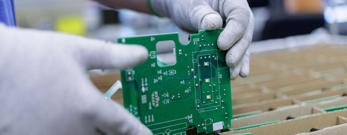
In Through-Hole Assembly, component leads are inserted through drilled holes in the PCB and soldered to pads on the opposite side or, depending on the component and process, to the same side.
The leads passing through the board provide a strong mechanical connection between the component and PCB. This makes through-hole technology particularly useful for components that experience mechanical stress, such as:
- Board-to-board connectors
- Wire connectors and terminal blocks
- Edge-mounted or mechanically stressed components
- Large electrolytic capacitors
- Transformers and inductors
- High-power components
- Components exposed to vibration or repeated insertion and removal
Wave Soldering and Selective Soldering
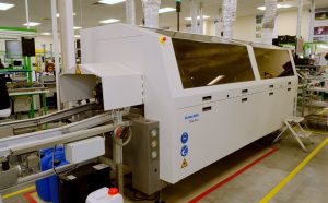
Wave soldering is a common automated process for soldering through-hole components. The PCB passes over a controlled wave of molten solder, allowing solder to contact exposed through-hole leads and pads.
However, wave soldering is not suitable for every mixed-technology design. When only specific through-hole areas need to be soldered while the PCB contains SMT components that should not be exposed to the solder wave, selective soldering can be used.
Selective soldering applies molten solder only to predetermined areas, making it particularly useful for mixed SMT and through-hole assemblies.
How Does SMT Assembly Work?
Surface Mount Technology (SMT) places components directly onto solder pads on the surface of the PCB rather than inserting leads through drilled holes.
A typical SMT process includes:
- Solder paste printing
- Solder paste inspection, when required
- Automated component placement
- Reflow soldering
- Automated optical inspection (AOI)
- Additional electrical or functional testing when required
Because SMT components are generally smaller than equivalent through-hole components, SMT enables higher component density and makes it practical to populate both sides of a PCB.
SMT is also highly compatible with automated production equipment, which makes it particularly suitable for medium- and high-volume PCB Manufacturing.
SMT vs TH: Key Differences
1. PCB Space and Component Density
SMT generally provides a significant advantage in component density.
Surface-mount packages can be very compact, and components can be placed on both sides of the PCB. Through-hole components require drilled holes, which consume board area and can restrict routing space, particularly on internal layers of multilayer PCBs.
For compact products such as wearable devices, smartphones, industrial controllers, and portable electronics, SMT is therefore often the primary assembly technology.
2. Mechanical Strength
Through-hole connections can provide stronger mechanical anchoring because the component leads extend through the PCB.
This can be valuable for components subjected to:
- Mechanical shock
- Vibration
- Repeated mating cycles
- Cable insertion forces
- Physical loads
For example, a connector that is frequently plugged and unplugged may benefit from through-hole mounting or a mechanically reinforced SMT connector design.
However, mechanical reliability depends on the component, PCB structure, solder joint design, mounting method, and application environment—not simply whether a component uses TH or SMT.
3. Thermal Performance
Through-hole component leads can sometimes provide an additional thermal path into the PCB, particularly when connected to large copper areas.
However, thermal performance depends on the complete design, including:
- Copper area
- Copper thickness
- Thermal vias
- PCB material
- Component package
- Heat-sink structure
- Airflow
- Power dissipation
For high-power applications, engineers may therefore use through-hole components, large copper structures, thermal vias, or specialized packages depending on the thermal requirements.
SMT components can also provide excellent thermal performance when designed with appropriate copper areas and thermal management structures.
4. Cost and Production Speed
SMT is generally more efficient for automated high-volume production.
Modern SMT lines can automatically print solder paste, place components at high speed, and perform reflow soldering with relatively little manual intervention.
Through-hole assembly may require additional component insertion and soldering operations. Depending on the design, these can involve:
- Manual insertion
- Automated insertion
- Wave soldering
- Selective soldering
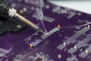
- Manual soldering
These additional processes can increase labor, equipment, setup, and inspection costs.
For high-volume products, minimizing unnecessary through-hole components can therefore help simplify the assembly process. However, replacing a through-hole component solely to reduce cost is not always appropriate if the component has important mechanical, thermal, or electrical requirements.
5. Component Availability
Most modern integrated circuits and many passive components are widely available in SMT packages.
Through-hole components remain common in connectors, switches, transformers, power components, terminal blocks, and applications where mechanical robustness is important.
Before selecting a package, engineers should consider the component’s:
- Availability
- Lifecycle status
- Lead time
- Alternative sources
- Unit cost
- Package compatibility
- Assembly requirements
Component availability should be evaluated as part of the overall PCB Design process rather than after the layout is completed.
What Is a Mixed-Technology PCB?
Many modern circuit boards use both SMT and through-hole assembly rather than relying exclusively on one technology.
A typical mixed-technology PCB might use SMT for:
- Integrated circuits
- Resistors
- Capacitors
- Diodes
- Small transistors
- Fine-pitch devices
While through-hole components may be selected for:
- Board-to-board connectors
- USB or other mechanically stressed connectors
- Terminal blocks
- Power input connectors
- Large electrolytic capacitors
- Transformers
- High-power components
This approach combines the compactness and automation advantages of SMT with the mechanical and application-specific advantages of through-hole assembly.
Mixed-Technology Assembly Process
A mixed-technology PCB requires careful process planning during the DFM stage.
A common production sequence is:
SMT solder paste printing → SMT component placement → reflow soldering → through-hole component insertion → wave or selective soldering → inspection and testing
The exact sequence depends on component placement and the manufacturer’s process capabilities.
For example, bottom-side SMT components must be evaluated carefully when wave soldering is planned. Components located in areas exposed to the solder wave may require special package selection, adhesive, orientation, or an alternative soldering strategy.
This is why assembly technology should be considered during PCB Design, rather than after the layout is finished.
How to Choose Between SMT and Through-Hole Assembly
There is no universal assembly technology that is suitable for every PCB. Engineers should evaluate the following questions during the design stage.
Does the Component Only Have an SMT Package?
If a required IC, passive component, or other device is only available in an SMT package, SMT assembly is the natural choice.
Is the Component Subject to High Mechanical Stress?
For connectors, terminal blocks, switches, or other components exposed to significant mechanical forces, through-hole mounting may provide useful mechanical reinforcement.
Is PCB Space Limited?
If board size and component density are critical, SMT is generally more suitable because of its compact packages and ability to populate both PCB surfaces.
Will the Product Experience Shock or Vibration?
For applications exposed to substantial vibration or mechanical shock, consider through-hole mounting or other mechanical reinforcement for critical components.
Is the Product Manufactured in High Volume?
For high-volume production, SMT can provide significant automation and throughput advantages. Reducing unnecessary through-hole operations can simplify the production process.
Are Thermal Requirements Critical?
Evaluate the complete thermal path rather than selecting SMT or TH solely based on package type. Copper thickness, thermal vias, copper planes, heat sinks, and component construction may all be more important than assembly technology alone.
How SMT and TH Affect PCB Manufacturing Cost
The choice between SMT and through-hole assembly affects more than component selection. It can change the complete PCB Manufacturing process.
Important cost factors include:
- Number of unique components
- SMT placement time
- Through-hole insertion requirements
- Stencil requirements
- Reflow process
- Wave or selective soldering
- Manual assembly
- Inspection requirements
- Test requirements
- Production volume
- Component availability
For example, a PCB using only SMT may require fewer assembly processes than a mixed-technology board. However, a mixed-technology design may still be the most practical solution when connectors, power components, or mechanically stressed parts require through-hole mounting.
The goal of cost optimization should therefore be to minimize unnecessary process complexity without compromising product performance or reliability.
Design for Manufacturability: SMT and TH Considerations
Design for Manufacturability (DFM) is especially important when a PCB combines SMT and through-hole components.
During a DFM review, engineers and manufacturers can evaluate:
- Component spacing
- Pad dimensions
- Component orientation
- Solder-joint accessibility
- Through-hole locations
- Wave-soldering compatibility
- Selective-soldering areas
- Thermal relief
- Test-point accessibility
- PCB panelization
- Component availability
- Assembly sequence
Good DFM practices can identify manufacturing problems before production begins, reducing rework, delays, and unexpected manufacturing costs.
SMT vs TH Assembly: Comparison Table
| Factor | SMT Assembly | Through-Hole Assembly |
|---|---|---|
| Component size | Generally smaller | Generally larger |
| Component density | High | Lower |
| PCB surface usage | Can use both sides | Typically requires more board area |
| Automation | Highly automated | Varies by process |
| Production speed | Generally high | Generally lower |
| Mechanical strength | Depends on package and design | Often strong for mechanically stressed components |
| High-volume production | Well suited | Suitable when application requires it |
| Fine-pitch components | Excellent | Limited |
| Connectors | Common, depending on mechanical requirements | Frequently used for mechanically stressed connectors |
| Power components | Widely used | Often useful for specific high-power designs |
| Typical soldering | Reflow | Wave, selective, or manual soldering |
| Best use case | High-density electronic assemblies | Mechanically or application-critical components |
How Kingda Can Support SMT and TH PCB Assembly
For custom PCB Assembly projects, assembly technology should be selected according to the product’s electrical, mechanical, thermal, sourcing, and production requirements.
Kingda can be positioned as a manufacturing partner for projects requiring PCB fabrication and assembly, with the assembly approach determined by the specific PCB design and production requirements.
Providing complete design and manufacturing information—including Gerber files, BOM, component specifications, assembly drawings, and relevant testing requirements—helps the manufacturer evaluate the appropriate SMT, through-hole, or mixed-technology process.
Conclusion
SMT and through-hole assembly are not necessarily competing technologies. In modern electronics manufacturing, they are often complementary.
SMT Assembly provides compact component packages, high component density, and strong automation advantages, making it suitable for many modern electronic products. Through-Hole Assembly remains valuable when components require additional mechanical anchoring, specific thermal characteristics, or application-specific construction.
For many custom PCB projects, the most practical solution is a mixed-technology design that uses SMT for densely packed electronic components and through-hole assembly where mechanical or application requirements justify it.
By considering assembly technology during the PCB Design stage and incorporating DFM principles before production, engineers can develop boards that balance functionality, reliability, manufacturing efficiency, and cost.