




Aerospace PCB Connectors: Selection and Reliability Guide
Aerospace PCB connectors must survive conditions that are far more demanding than a normal commercial environment. Spacecraft, satellites, and interplanetary systems face radiation, extreme temperatures, and strong vibration during launch. The connector is a critical link between circuit boards, power systems, and mission electronics, so the selection process directly affects system performance and reliability.
Looking at the night sky may make space seem quiet, but orbital and interplanetary environments are harsh for electrical systems. Electronic boards are protected to some extent by the spacecraft structure, but they are not immune to radiation particles and thermal stress.
This guide explains the hazards of space PCB interconnection and the factors to consider when choosing aerospace PCB connectors.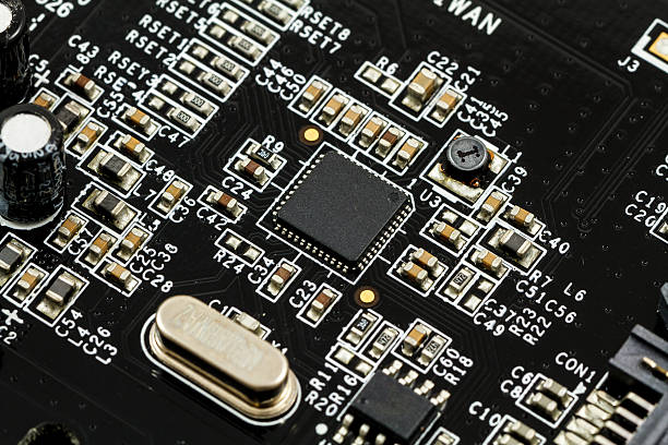
The Space Environment
Space includes every altitude above or beyond the Earth. The atmosphere has different layers, and each layer presents different environmental conditions for an electronic platform.
A connector used in low Earth orbit may experience a different environment from one used in interplanetary space. Temperature, radiation, vacuum, and contamination levels can all change the behavior of the connector.
The selection process should begin with a clear definition of the mission environment rather than with a general connector catalog.
Spacecraft circuit board interconnection is one of the most demanding applications in electronics because repair is usually impossible after launch.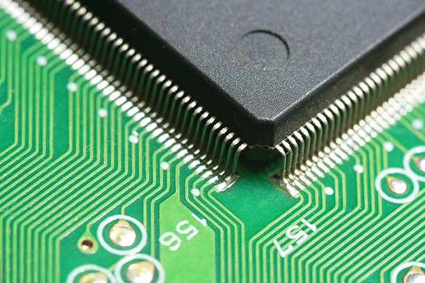
Vibration and Shock Hazards
Vibration is one of the biggest concerns for all spacecraft systems. The strongest vibration and shock occur during launch, when the rocket engines and aerodynamic forces act on the complete structure.
Vibration can fracture connector pins, deform contact surfaces, and create transient signal interruptions. Repeated vibration can cause metal fatigue that appears only after the spacecraft has been operating for a long time.
The connector must be mechanically secured to the board and structure so that its contacts do not move during launch. Standoffs, mounting screws, and strain relief all contribute to the mechanical design.
Test programs should include vibration and shock profiles that match the expected launch environment.
Extreme Temperature Hazards
Extreme temperature is another major hazard for aerospace PCB connectors. The risk is often internal as well as external because the spacecraft itself generates heat while the cold space environment removes it.
During launch, temperatures near the rocket engine can rise above 3000 degrees Celsius. These temperatures exceed the limits of PCBA materials and most avionics components.
Thermal isolation and active thermal control are essential for the spacecraft. The connector must operate over the temperature range of the electronics bay, including the temperature changes that occur when the spacecraft moves between sunlight and shadow.
The coefficient of thermal expansion of the connector, board, and housing should be compatible so that thermal cycling does not create cracks or intermittent contacts.
Radiation Hazards
High-energy ionizing radiation is one of the most dangerous hazards in space. Radiation exists beyond the protective atmosphere and can penetrate almost any material.
Radiation particles can cause charge to accumulate on conductive elements or displace atoms in semiconductor materials. This can change the electrical behavior of the circuit and produce single event effects.
Circuit board designers use radiation-tolerant components and shielding to reduce the risk. The connector must also be selected for radiation resistance, especially when its insulating materials are exposed to high total dose.
Radiation testing should be part of the qualification plan for mission-critical connectors.
Connector Type and System Compatibility
There are many aerospace PCB connectors available, and choosing the best type cannot be based on a simple recommendation. The connector must be selected together with the other circuit boards or electronic equipment that it will connect to.
The engineer should understand the signal type, data rate, current, and voltage required for each connection. Power connectors, signal connectors, RF connectors, and high-speed data connectors have different design requirements.
Mechanical factors such as housing clearance, wiring space, cable routing, and alignment of the connector holes must also be reviewed. A connector that is electrically correct but mechanically unsuitable will fail in assembly or service.
The board layout should provide the correct footprint, mounting holes, and keep-out area for the selected connector.
Regulatory Requirements
Connectors used on aerospace platforms must meet the material and test requirements specified by industry standards. Standards such as EIA/ECA-364-18B and EIA-364-13E define tests for the connector under specific conditions.
Additional standards cover continuity during mechanical shock, durability of mating and unmating, and the test programs for the installation environment.
The connector supplier should provide qualification data and traceability for every lot. A part that passes a commercial test may not meet the stricter requirements of an aerospace program.
The compliance record should be reviewed during component selection and again when the part is received at the factory.
External Environmental Conditions
For external cables and connectors, temperature range and radiation exposure are the main considerations. The connector may be mounted on the outside of the spacecraft or on a structure that is directly exposed to space.
External connectors must tolerate large temperature swings, ultraviolet radiation, atomic oxygen in low orbits, and vacuum outgassing.
The connector materials should have low outgassing so that volatile compounds do not condense on optics or other sensitive surfaces. Surface finish should resist corrosion and maintain low contact resistance.
Internal Environmental Conditions
Internal connector environments include the temperature range inside the electronics bay, humidity changes, electromagnetic interference, and any radiation that penetrates the spacecraft structure.
The connector should provide consistent contact resistance over the internal temperature range. Moisture that condenses during ground handling or launch can create corrosion if the connector is not sealed properly.
EMI shielding may be required around high-speed or sensitive signals. The connector shell and backshell should provide continuous shielding from the cable to the board.
Internal connectors may also be exposed to vibration transmitted through the spacecraft structure even when they are not on the external surface.
Operational Requirements and Service Life
Most spacecraft electronic systems cannot be repaired or replaced after launch. The connector must meet its performance requirement for the complete mission life without maintenance.
The engineer should define the expected number of mating cycles, operating current, signal integrity limit, and environmental lifetime before the connector is selected.
Derating is important in aerospace design. The connector should be operated below its absolute maximum current and temperature so that aging and environmental stress do not reduce its margin.
Long-duration missions may also require the connector to survive radiation exposure that accumulates over many years.
Supply Chain and Traceability
Parts supply chain management is a major concern for aerospace PCBA. Counterfeit or unqualified connectors can create a hidden risk that is very difficult to detect after the board is installed.
The factory should buy aerospace connectors only from qualified suppliers and use a digital supply chain to track every component from purchase to assembly.
Lot codes, date codes, certificates of conformance, and inspection records should be stored with the board history. This traceability is required for aviation regulations and quality management system tracking.
If a supplier changes its manufacturing location or material, the change must be reviewed before the new lot is used in production.
Design for Manufacturing and Test
Aerospace PCB connector selection should be integrated with the PCBA design process. The board layout must support the connector footprint, mechanical support, and thermal requirements.
DFM checks should confirm that the connector can be soldered reliably, inspected, and tested in the selected assembly process. Rework of a mission-critical board should be avoided whenever possible.
Test points should provide access to the connector circuits so that continuity, isolation, and signal quality can be verified after assembly.
The design files should include the connector part number, supplier, finish, and qualification status so that the assembly factory does not substitute an unapproved part.
Working With a Qualified Assembly Partner
A high-reliability PCB assembly service should have experience with aerospace components and quality records. The factory should handle connectors according to ESD, moisture, and contamination requirements.
The soldering process must be suitable for the connector terminal material and the aerospace PCB finish. The SMT PCB assembly line should be capable of placing and reflowing the selected connector without damaging its housing.
After assembly, the boards should be inspected and tested according to the program requirement. PCBA testing should include continuity, isolation, and functional checks for the connector circuits.
Documentation and quality management records should support the complete build so that the customer can trace every board back to its connector and component lots.
When a connector is exposed to repeated thermal cycles, the contact resistance can slowly increase. The design should include a sufficient number of contacts and use gold or other noble plating for low-energy signals. A protective conformal coating may be applied around the connector pins after inspection, but it must not cover the mating surface or prevent later test access.
All qualification and test data should be reviewed again when the production quantity changes or when the connector is used in a new mission. The goal is to prevent an unapproved change from entering the space hardware after the original design was qualified.
Conclusion
Aerospace PCB connectors must satisfy strict electrical, mechanical, environmental, and traceability requirements. Vibration, extreme temperature, and radiation all affect how the connector will perform.
Selection should be based on the mission environment, connector type, regulatory standards, and operational service life. The supplier and assembly chain must provide full traceability for every part.
With careful selection and qualified manufacturing, aerospace PCBA connectors provide reliable power and signal connections throughout the life of the spacecraft.


