AOI Lighting: 6 Setup Rules to Cut False Calls
AOI lighting is the arrangement of light sources that illuminates a board for the inspection camera, and it is the part of the machine that decides what the software is allowed to see. A solder joint that is never lit correctly cannot be judged, and a joint lit two different ways on the same panel produces calls that have nothing to do with the process.
Most systems offer several colours and several angles, sometimes inside one head. Choosing between them is a process decision rather than a machine setting, because the choice changes which features stand out and which defects disappear into the background of the image.
What AOI Lighting Has to Reveal
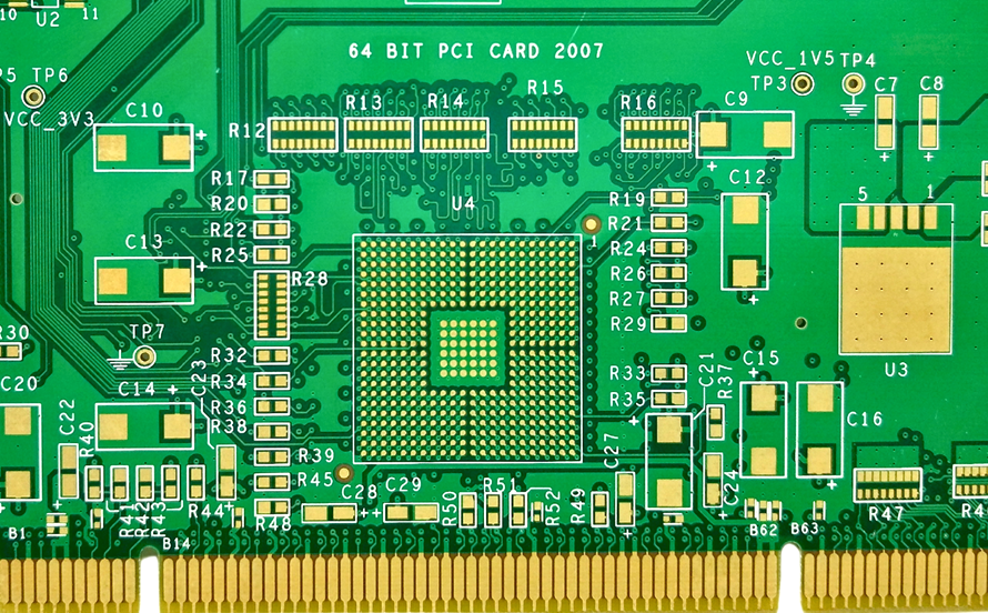
The camera has to show the shape of a fillet, the presence of a component, the edge of a pad and the contrast between metal and mask. Those features sit on a surface that ranges from bright copper to matt black, so a single setting rarely serves a whole board.
A program that relies on one setting is strong in one area and blind in another. The usual result is a high false call count in the bright regions and missed defects in the dark ones, and both are blamed on the camera rather than on the light that feeds it.
Angle, Colour and the Joint Surface
Low angle light grazes the board and picks up relief, which is what a solder joint fillet has. High angle light floods the surface and shows colour and coverage, which suits presence and polarity checks. Mixing the two in one image is a compromise that has to be deliberate.
Colour separates materials. A red and blue pair makes a solder joint read differently from the mask and from the pad, and that separation lets a simple threshold judge the joint. A mono setup can do the same work, but it demands much more careful angle selection.
Setting Intensity Without Burning the Image
More light is not automatically better. Once the sensor saturates, the fillet loses its shape, and a specular highlight on a shiny joint can look like a void. Intensity and exposure should be set together so that the brightest feature on the board stays below saturation.
A grey card or a known reference pad can be used to check the level, and the check belongs in the calibration routine rather than in a setup sheet that nobody reads. Our AOI calibration notes describe the reference surfaces used for that work.
False Calls and the Lighting Balance
A false call is a rejection that later inspection clears, and lighting is one of its most common causes. A shadow across a joint, a reflection from a nearby component or a colour shift on a different finish all produce readings that fall outside the learned limits.
Cutting the count is a matter of consistency before sensitivity. Two boards of the same product should be lit identically, and a marginal area should be solved with a better angle rather than a looser threshold. Our false call notes explain how the limits are set.
Camera Angle and the Component Shadow
Tall components cast shadows, and the shadow moves with the camera angle. A sequence that views a joint from one direction only will miss a defect hidden behind a shield, while a sequence with two angles sees it and doubles the image processing time.
The choice should follow the defect history of the product. A board with fine pitch parts under a shield earns the second angle, while a simple board with generous spacing may not. The decision belongs in the program notes so that it survives the next edit.
Lighting Drift, Dust and LED Age
LED output falls slowly, and dust on a lens or a diffuser cuts brightness unevenly. Neither failure announces itself, so the program gradually works with a dimmer and less even image until a defect escapes or the false call rate climbs without an obvious reason.
Cleaning the optics on a fixed interval and comparing the image against a reference board keeps the system honest. Where the machine stores a reference image, a visual comparison over time shows the drift without any instrument. Our inspection comparison notes describe where optical checks reach their limit.
Matching Lighting to the Inspection Program
Every setting should be tied to a program and a product, and the program should record which one was used. When a program is copied to a second machine with different optics the settings do not transfer, so a copy that looks correct on screen will inspect differently on the line.
The safe approach is to treat lighting as a recipe item, like the profile in a reflow oven. Copying a program without its recipe is a change that must be verified on a board with known defects before the line runs production. Our inspection program notes cover the tuning sequence.
Training the Operator to Read the Image
An operator who can tell a real defect from a lighting artefact saves the line more time than any threshold change. That judgement comes from seeing the same board under good and bad lighting, which is easy to arrange with a reference board and a manual intensity control.
The training should include the defects the product actually produces, because a general course does not prepare anyone for a specific board. A short session at the machine, with the machine in production mode, is worth more than a day in a classroom.
Records and Change Control
The record should show the lighting recipe, the intensity and exposure at release and the date of the last optical clean. A defect that escapes six months later is investigated against that record, and without it the discussion is only opinion.
Any change to a light source, a diffuser or a camera is a change to the inspection process and should be re-verified on a known board before release. The acceptance criteria for the joints themselves stay with the customer specification, and the IPC assembly standard is the usual reference for those limits.
Lighting for a Mixed Technology Board
A board that carries through hole parts and fine pitch devices asks the light to do two jobs at once. The through hole joints are large and uneven, so they need grazing light to show the fillet, while the fine pitch row needs even, controlled light to show a bridge between two leads.
Where the two cannot be satisfied in a single pass, the product can be inspected in two passes with different recipes. The extra cycle time is usually cheaper than the escapes that a single compromise setting allows, and the customer sees a defect history rather than an argument.
FAQ
Can one lighting recipe cover several products? Often it can, if the boards share a finish and a similar component mix. Where they do not, a shared recipe produces false calls on one product and escapes on another, so the recipe should follow the product family rather than the machine.
Should the lighting be re-tuned when a program is updated? Only if the update changes the features being inspected. A change to a threshold or a window does not need new lighting, while a change of camera, lens or diffuser does, because the image the software receives is different.
Why do false calls rise after a lamp replacement? Because the new source is brighter than the old one that the recipe was taught with. Re-teaching the reference values after a replacement, rather than loosening the limits, keeps the program and the hardware in step.