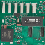
The Assembly Drawing and What It Must Carry
An assembly drawing is the document that tells the production floor what to build, and it is usually the least maintained document in the package. Where it is wrong, the board is built wrongly and the mistake is invisible until test.
What the Assembly Drawing Carries
The drawing shows the board outline with the reference designators and the component outlines positioned as they are on the board, together with the polarity marks, the pin-one indicators and the notes that apply to the assembly.
It is not a substitute for the fabrication drawing, which describes the bare board, and the two should be consistent. A change to the placement affects both, and a package in which only one has been updated produces a board that matches neither. Our design release checklist lists the documents.
Polarity and Orientation
Every component with a polarity or a preferred orientation needs a mark that is visible after the component is fitted. A mark that is under the component body is useless, and a mark that relies on the silkscreen being legible over a pad is unreliable.
The convention should be consistent across the board and across the product family. A design where pin one is marked differently on two similar packages invites an error at the machine.

Keep-Outs and Height Restrictions
Where a component must not exceed a height, or where an area must remain clear for a mechanical feature, the drawing is where that is recorded. A height restriction that exists only in a mechanical model is a restriction the assembly line does not see.
The same applies to components that must not be reflowed, must not be washed, or must be fitted after the wash. Those instructions change the assembly sequence and belong on the drawing.
Notes That Change the Process
A short notes block covers the items that change what the line does: the solder alloy, the cleaning requirement, the coating, the torque for a fastener and the identification marking. Each of those is a process instruction rather than a preference.
Where a note is conditional, the condition should be stated. An instruction to torque a fastener without a value is not an instruction.

Revision and Change Marking
The drawing should carry the revision of the board it describes, and a change to the placement should be marked so that the line can see what moved. A change that is not marked is a change that will be missed on a board that is already in production.
The revision of the assembly drawing and the revision of the bill of materials must correspond. Where they diverge, the line is building to two conflicting instructions.
Test and Inspection Requirements
Where a specific inspection is required, such as an X-ray of an area array package or a visual check of a particular joint, the drawing is where the requirement is recorded. The inspection plan references the drawing rather than the other way round.
The requirement should name the feature and the acceptance criterion rather than the method alone. Saying that a joint must be inspected does not say what makes it acceptable.
Where the Drawing Goes Wrong
The common failures are a drawing that was never updated after a placement change, a polarity mark that is hidden by the component, a height restriction that is not recorded at all, and notes that contradict the bill of materials.
Each of those produces the same outcome: the line builds what the drawing says, the board fails a check, and the investigation begins with the assumption that the drawing is correct. Our board quality notes describe how the discrepancy is found.
Keeping the Package Consistent
The practical discipline is to treat the drawing, the bill of materials and the fabrication data as one package that is released together and revised together. A change to any one of them triggers a check of the other two.
Where the package is supplied to an assembler, the revision in use should be confirmed at the start of the build. That confirmation is a minute’s work and it prevents a batch being built to a superseded instruction.
Process Control and Verification
On a design of this kind, revision is the item that decides how the rest of the board is arranged. Where the requirement is not written down, the shop supplies its own default, and the default is chosen for the process rather than for the design. The measurements that matter are the repeatable ones: conductor width and spacing, annular ring, finished hole size, plating thickness and surface finish are all verifiable on a coupon that travels with the panel.
Running a first article through the same checks as the production panel confirms that the two agree, and that comparison is the cheapest form of process control available at prototype stage. Keeping a sample from the panel turns a dispute into a measurement, because the same coupon can be re-examined by both parties without rebuilding the batch.
Reviewing the design before the data is released is cheaper than correcting it after the panel is in the tank, because every step downstream inherits the decision made at the front end. Documenting the assumption is part of the design work, and a short note on the drawing prevents a question that would otherwise arrive a day later and cost a day of schedule.
Related reading: our fabrication notes, board quality and design release notes cover the same ground.
Process Control and Verification
On a design of this kind, revision is the item that decides how the rest of the board is arranged. Where the requirement is not written down, the shop supplies its own default, and the default is chosen for the process rather than for the design. The measurements that matter are the repeatable ones: conductor width and spacing, annular ring, finished hole size, plating thickness and surface finish are all verifiable on a coupon that travels with the panel.
Running a first article through the same checks as the production panel confirms that the two agree, and that comparison is the cheapest form of process control available at prototype stage.
Process Control and Verification
On a design of this kind, revision is the item that decides how the rest of the board is arranged. Where the requirement is not written down, the shop supplies its own default, and the default is chosen for the process rather than for the design. The measurements that matter are the repeatable ones: conductor width and spacing, annular ring, finished hole size, plating thickness and surface finish are all verifiable on a coupon that travels with the panel.
FAQ
Can the assembly drawing be a screenshot of the layout? It can be a plot from the layout tool, which is better because it is generated from the same data as the board. A screenshot is a copy, and a copy is a document that can diverge from its source.
Who owns the drawing? The design authority, because it contains decisions about polarity, height and process that are engineering decisions rather than assembly preferences. The assembler may propose additions, but the approval belongs to the design.
What does gopcb check on an assembly drawing? We check that the reference designators match the bill of materials and the layout, that polarity marks are visible after assembly, that height restrictions are recorded and that the notes are consistent with the fabrication drawing. Any conflict is reported before the build.