Auto-Insertion Process Control for Through-Hole Assembly
Auto-insertion is the mechanised placement of through-hole parts, and it succeeds or fails on mechanical tolerances rather than on electrical ones. The machine pushes a lead into a hole with a defined force, and if the lead span, the hole position and the clinch tooling are not aligned, the lead buckles, the pad lifts, or the part sits above the board on a bent lead.
The process is worth controlling carefully because it is fast and unforgiving. A mis-set insertion depth on a sequencer can damage a thousand boards before anyone notices, and the damage is often internal to the laminate rather than visible on the surface of the joint.
What Auto-Insertion Covers
The process takes components from tape or from a stick magazine, forms the leads, inserts them into the board and clinches them underneath. Radial machines handle capacitors and similar parts, axial machines handle resistors and diodes, and both rely on the component lead being formed to the same span as the hole pattern.
Every step has a tolerance that interacts with the others. Tape pitch affects the feed position, the lead form affects the span, the anvil position affects the clinch, and a small error in each adds up to a part that is inserted at an angle or not at all.
Component Sequencing and Taping
Sequencers tape axial parts into a programmed order, and the tape pitch and the tape width have to match the machine as well as the component. A tape that is 0.2 mm thinner than the specification will sit lower in the track and feed the part at the wrong moment.
Taping also fixes the component pitch on the board, so a change of tape pitch is a change of the insertion program. Where a supplier changes the taping without notice, the first boards of the lot are the ones that will show the fault, which is why the incoming check on taped stock is worth more than its cost.
Lead Forming and Span Tolerance
Lead forming sets the span between the leads and the height at which the body will sit. A span that is slightly too wide will not enter the holes, and a span that is slightly too narrow will enter but will push the hole walls outward, loading the barrel and the pad in a way the design did not intend.
Forming tools wear, and the wear appears as a gradual change in span rather than as a step. Measuring the span on a sample of formed parts every shift is therefore a practical control, and it should be recorded against the tool as well as against the product.
Insertion Force and Lead Splay
Insertion force is set by the machine and should be just enough to seat the part, with the anvil below the board receiving the leads. Too much force bows the board and can leave a crack in the resin under the pad, while too little leaves the part standing proud of the surface.
Splayed leads are the visible symptom of a force that is too high or an anvil that is out of position. Where the leads deflect outward instead of entering the holes, the machine is pushing against the board rather than into it, and the cause is usually the board support height rather than the insertion head itself.
Radial and Axial Machine Differences
Radial machines index the board to a fixed head and insert with a vertical stroke, while axial machines form a bridge or a stand-off in the lead and often place the part flat against the board. The two need different support tooling and different clinch settings.
Axial parts are more sensitive to board support, because the forming operation applies a bending moment to the lead before insertion. Where the support pins miss a hole-free area of the panel, the board flexes during forming and the resulting lead height varies across the panel, which then shows up in the carrier and support set-up rather than in the machine.
Clinching and Cut-Off Tooling
Clinch tooling bends the leads under the board so that the part stays in place through wave soldering. The clinch angle, the clinch length and the direction of the bend are all specified, and a clinch that is too short lets the part move, while one that is too tight can crack the laminate.
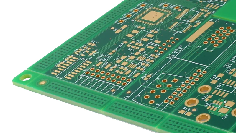
Cut-off blades work alongside the clinch tool and wear in the same way. A dull blade shears rather than cuts, which leaves a burr on the lead end and applies a shock load to the pad, and the effect on the joint is visible in the barrel fill result after wave soldering.
Placement Verification and First Article
Verification should confirm four things: that the part is the correct value, that it is oriented correctly, that it is seated on the board, and that the clinch is formed in the specified direction. A first article check on the first board of every run covers all four in a few minutes.
Polarity is the check that is most often missed, because a radial capacitor inserted in the wrong orientation still looks correct from above. The inspection should view the board from both sides, since the clinch direction and the lead length are only visible from underneath.
Defects and Their Causes
The common defects are a part sitting high, a bent or splayed lead, a lifted pad, a cracked laminate under the pad and a missing clinch. Each maps to a small number of causes, and the mapping is what makes the corrective action quick.
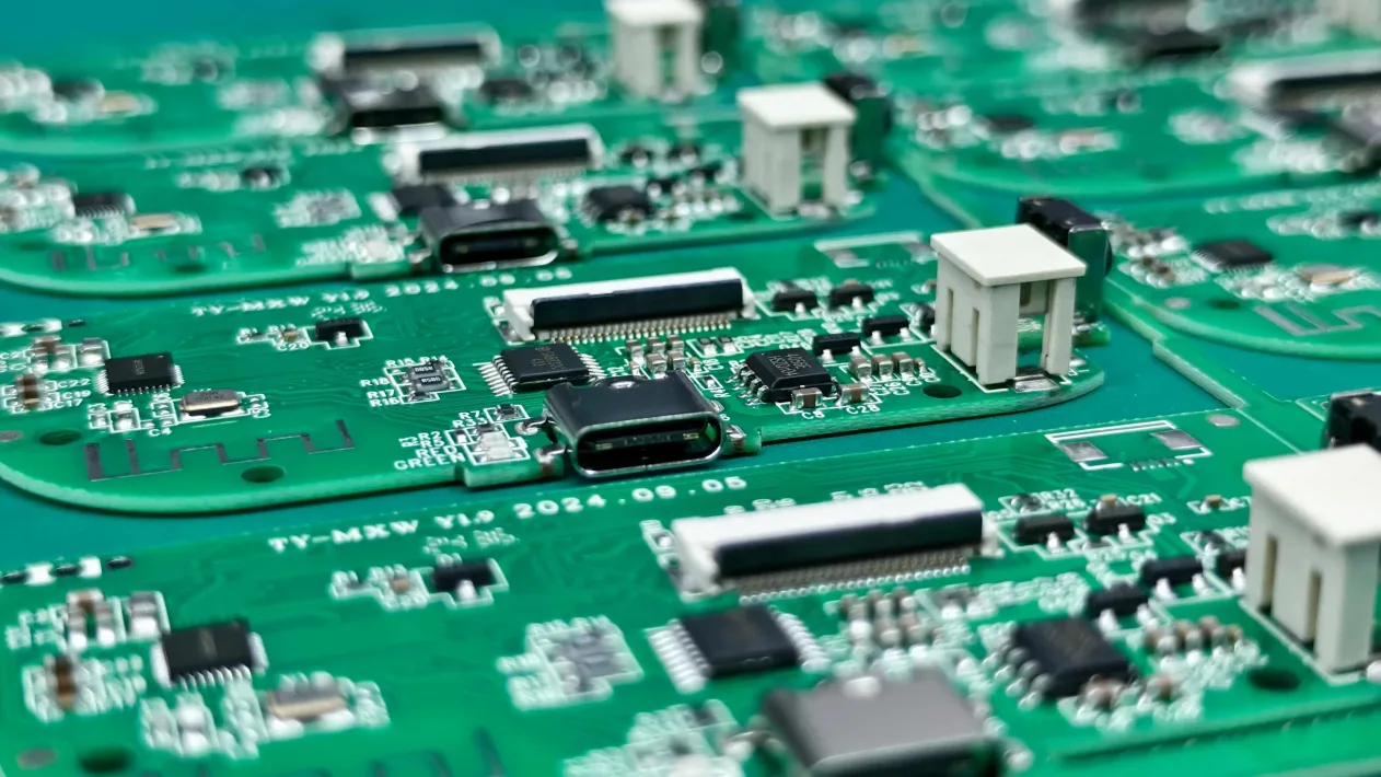
A part sitting high points to insertion depth or to a lead that has not been formed correctly. A lifted pad points to force or to a support pin in the wrong place. A missing clinch is usually a tool that has jammed, while splayed leads point to the anvil height, and the wave height and board contact conditions are checked afterwards to confirm that the joint itself was formed as intended.
Records and Process Limits
Records should name the machine program, the forming tool, the clinch setting, the insertion force and the board support layout. Where a product runs on two machines, both should be compared on the same day rather than assumed to be equivalent.
Process limits should be expressed as measurements rather than as machine numbers: seated height above the board, lead span, clinch angle and insertion force. Machine numbers change when a head is replaced, while measurements stay comparable, which is what makes the record useful across the life of the product.
FAQ
Why do auto-inserted parts sit high above the board? The usual causes are an insertion depth that is too shallow, a lead that has not been formed to the correct height, or a support pin that is holding the board away from the anvil.
How is span tolerance controlled in auto-insertion? By measuring the formed span on a sample of parts each shift and recording the result against the forming tool, since tool wear changes the span gradually rather than suddenly.
Can auto-inserted joints be clinched too tightly? Yes. An over-tight clinch loads the laminate around the hole and can crack the resin, which appears later as a lifted pad or as a barrel crack after thermal stress.