automotive LED PCB: Design and Assembly Considerations
Automotive lighting is moving quickly from halogen and HID lamps to LED systems because LEDs deliver better efficiency, faster response, and more flexible light design. Behind every reliable LED headlamp, taillight, and interior lamp is an automotive LED PCB that carries current, controls each light channel, and removes heat from the LED junction so the lamp keeps working under demanding vehicle conditions.
Aluminum Base Materials for LED Boards
Most automotive LED lighting boards are built on aluminum-base copper clad laminates.
The same discipline applies to automotive LED PCB, where a small process drift turns into a large yield loss.
The structure combines an aluminum plate, an insulating dielectric layer, and copper foil. Aluminum spreads heat quickly away from the LED package, while the copper layer provides circuit paths and further dissipates heat into the surrounding air. This structure keeps component temperatures lower during long hours of operation.
Lightweight and Compact Board Design
Aluminum-based LED PCBs are lighter and thinner than traditional glass-fiber boards, which supports the lightweight design goals of modern vehicles.
Multiple LED packages and optics can be placed on a compact board inside headlamp and taillight housings. A smaller, thinner circuit also gives styling and packaging teams more freedom when integrating lighting into the vehicle body.
Reviewing automotive LED PCB before the first article is built saves rework later in the run.
Surface Finish and Microvia Design
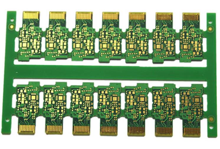
Lead-free HASL is a common finish for automotive LED lighting PCBs because it is environmentally friendly, solderable, and oxidation-resistant. Small controlled hole sizes and conical hole shapes improve soldering reliability, support thermal transfer, and make assembly easier. Board thickness, copper thickness, and hole diameter should be selected with the LED current and mounting method in mind.
Thermal and Electrical Reliability
An automotive lamp can run for hours in hot engine compartments, through sunlight, and in freezing weather. The PCB must maintain strong insulation, good solder joints, and stable thermal paths under these conditions. Thermal via patterns, adequate copper area, and correct pad design help keep the LED junction cool and prevent premature light output degradation.
Documenting automotive LED PCB keeps assembly, inspection and test teams working from the same numbers.
Practical Checklist
Use this short review when the design moves from quotation into production.
- Aluminum Base Materials for LED Boards: record the agreed limits and verify them again in the production lot.
- Lightweight and Compact Board Design: check the drawing, process sheet and inspection plan before release.
- Surface Finish and Microvia Design: treat this as a repeat-order checkpoint and keep the result with the lot record.
- Thermal and Electrical Reliability: review the production data and close any deviation before the next build.
- Manufacturing Support for LED Lighting Projects: confirm the requirements, process settings and inspection records at first-article approval.
- Repeat-order consistency: record the agreed limits and verify them again in the production lot.
Manufacturing Support for LED Lighting Projects
LED lighting designs benefit from early DFM review because solder mask, thermal relief, and routing choices affect both assembly yield and long-term reliability. Working with a manufacturer that understands aluminum boards also helps you select the right material, panel layout, and surface finish before production begins.
gopcb supplies automotive and LED lighting projects with PCB manufacturing, design-for-manufacturability support, and high-volume PCB assembly, giving your lighting design a reliable path from prototype to production.
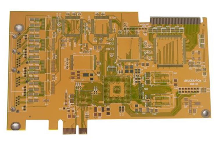
For automotive LED PCB, the figures that matter are measured rather than assumed.