Board Edge Clearance Rules for Assembly
A board edge is a boundary with several requirements attached to it. Components must stay back from the edge for handling, copper must stay back for routing and plating, and fiducials and tooling features must sit within defined zones.
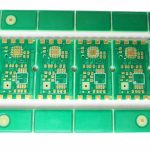
These rules are usually expressed as clearances from the outline, and they change with the assembly process. A board that will run over a conveyor rail needs more space than one that is held in a fixture, and a panel that is broken apart needs a zone that is free of everything.
Conveyor Rails and Tooling
A conveyor grips a strip along the two long edges of the panel, and no component or solder joint may sit inside it. The width is machine dependent and typically between three and five millimetres.
Where the product is processed in a fixture or a carrier, the restriction applies to the fixture instead, which may allow a smaller board edge clearance. The choice should be made with the process rather than with the product alone.
Component Keep Out
Components need clearance from the edge so that the board can be handled, depanelised and installed without touching them. A part placed within a millimetre of a V-cut is at risk from the breaking tool and from the burr that the break leaves.
The keep out should also account for the housing, because a board that slides into a groove needs clearance along the edges it slides on. That requirement is mechanical rather than electrical and is often discovered at first fit.
Copper and Mask Clearance
Copper is normally pulled back from the outline so that the router does not cut through it and leave a burr or an exposed conductor. The pull back is a fabrication rule and it varies with the finish and with whether the edge will be plated.
Where edge plating is required, the rule is inverted and the copper is brought deliberately to the edge as described for edge plating requirements. The two requirements cannot coexist on the same edge without a clear specification.
Fiducial Zones
Fiducials need a clear area around them so that the camera sees a contrasting shape rather than a busy surface. The clear area is typically of the same order as the fiducial diameter, and no mask or copper feature should intrude into it.
Panel level fiducials should be placed near the corners and outside the board outline, while board level fiducials are placed inside the outline where the machine can see them after depanelling.
Tooling Holes and Locating Features
Tooling holes are used by the printer, the placement machine and the test fixture, and they should be specified once rather than added by each station. They need a keep out of their own so that no component interferes with the pin.
The hole size and tolerance should be defined against the pin rather than chosen freely, because a hole that is slightly too large allows the board to shift and defeats the purpose.
Break Lines and Separation Zones
The area along a break line has to be free of components and of fine features, because the separating force travels through the laminate. Mouse bites leave small bumps that can interfere with a mating surface.
Where a component must sit close to the edge, the panel layout can add material outside the finished outline so that the force is absorbed elsewhere. This is a panel design solution to a mechanical problem.
Silkscreen and Marking
Legend and marking should also stay clear of the edge, both because the ink can be removed by handling and because a marking that is cut in half is unreadable. Revision markings that will be inspected should be placed well inside the outline.
The same applies to a barcode or a data matrix, which needs a quiet zone of its own that no mask or copper feature may enter.
Routed Slots and Internal Edges
An internal cutout has the same requirements as an outer edge, including copper pull back and component clearance. A connector that is mounted in a cutout needs clearance on all four sides and a defined tolerance on the cutout itself.
Slots that are narrow relative to the board thickness are harder to route and may need a different process, so the width should be checked against the fabrication capability.
Documentation
The assembly drawing should show the keep out zones rather than describing them in text, because a drawing is unambiguous and a sentence is not. The fabrication drawing should carry the copper pull back and the tooling holes.
Where a keep out is required for a mechanical reason such as a screw boss or a connector body, the component that creates the requirement should be shown on the drawing. This is the kind of item that belongs in the design release review.
Process Control and Verification
On a design of this kind, component keep out is the item that decides how the rest of the board is arranged. The process window is set by the narrowest step in the flow, so an improvement anywhere else shows up as margin rather than as yield until that step is addressed. A short note on the drawing about handling, storage or packaging is often worth more than an extra decimal place on a tolerance.
Where a value sits close to a process limit, the drawing should say so, since the shop can then open the process window rather than working to a nominal figure that carries no tolerance. A stack-up that is drawn rather than described removes most of the ambiguity from a quotation, and it lets the fabricator price the board against the dielectric and copper weights that will actually be used.
Where the requirement is not written down, the shop supplies its own default, and the default is chosen for the process rather than for the design.
Related reading: our fabrication notes, board quality and design release notes cover the same ground.
Process Control and Verification
On a design of this kind, component keep out is the item that decides how the rest of the board is arranged. The process window is set by the narrowest step in the flow, so an improvement anywhere else shows up as margin rather than as yield until that step is addressed. A short note on the drawing about handling, storage or packaging is often worth more than an extra decimal place on a tolerance.
Process Control and Verification
On a design of this kind, component keep out is the item that decides how the rest of the board is arranged. The process window is set by the narrowest step in the flow, so an improvement anywhere else shows up as margin rather than as yield until that step is addressed. A short note on the drawing about handling, storage or packaging is often worth more than an extra decimal place on a tolerance.
A first article check confirms that the process and the drawing agree on the points listed above, and that the coupon data supports the values used in the design.
Where a measurement falls outside the expected window, the sample is retained so that the cause can be established before the balance of the batch is released.
A first article check confirms that the process and the drawing agree on the points listed above, and that the coupon data supports the values used in the design.
Where a measurement falls outside the expected window, the sample is retained so that the cause can be established before the balance of the batch is released.
FAQ
How much edge clearance is enough? Enough to satisfy the conveyor, the depanelising method and the housing at the same time, which is usually the largest of the three figures.
Can components be placed over a mounting hole? No, because the hole is used by a fastener or a pin that must seat flat against the board.
Do internal cutouts need the same rules? Yes. The cutout is an edge for every purpose, including copper pull back and component clearance.
Where should fiducials be placed? In an area with clear contrast, away from mask features and vias, and at a position the machine can reach before the first placement.